Unbox the Machine
| Model | [•] AON M2+ (CE) | [•] AON M2+ (R-NZ) | [•] AON M2+ | [•] AON-M2 2020 | [•] AON-M2 |
| Category | [•] Installation | [ ] Operation | [ ] Maintenance |
Summary
The procedures that follow gives instructions on how to:
- Unbox the AON3D machine from the crate.
- Move the AON3D machine to its designated work location.
- Level the machine.
- Put the vacuum pump on the floor. (only applicable to the AON M2+ (CE) and AON M2+ (R-NZ) machines)
Estimated time: 45 minutes
Tools
| Qty | Description | Specification |
|---|---|---|
| 1 | Hammer, Claw | Optional |
| 1 | Screwdriver | Phillips, No.2 |
| 2 | Wood Screws | 1 inch length, Phillips No.2 |
| 1 | Spirit Level | N/A |
| 1 | Camera, Digital | N/A |
| 1 | Hex Key | 4 mm |
Parts Information
None required.
Personal Protective Equipment
| Qty | Description | Minimum Specification |
|---|---|---|
| 1 | Safety Eyewear | ANSI/ISEA Z87.1 |
| 1 | Safety Footwear | N/A |
| A/R | Nitrile Gloves | ISO 2859-1 or ASTM D6319 |
| A/R | Gloves | Work |
Examine the Shipping Indicators
The AON3D warranty will come in effect upon the date of reception of the machine. In order for AON3D to respect this warranty, the customer must provide clear photographs of the ShockWatch® 2 and the two TiltWatch® Plus indicators to our Customer Success team at help@aon3d.com. Make sure that your Reception Department (Shipping & Receiving) has been made aware of the importance of providing our Customer Success team with above-mentioned photographs.
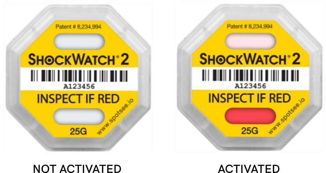
- Examine the ShockWatch® 2 indicator, found on the rear panel of the shipping crate.
- Take a clear photograph of the ShockWatch® 2 indicator and note if one of the two top and/or bottom windows are red.
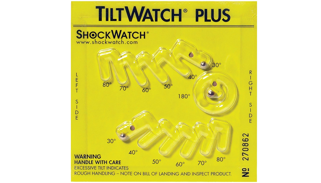
- Examine the two TiltWatch® Plus indicators located on the crate’s exterior panel.
- Take a clear photograph of the two TiltWatch® Plus indicators and note if a tilt greater than 30 degrees has been recorded.
- Send photographs of all three indicators to our Customer Success team at help@aon3d.com.
If either of the ShockWatch® 2 indicator windows are red, and/or if either one of the two TiltWatch® Plus indicators show(s) a tilt greater than 30 degrees, the machine may have been damaged in transit. Reach out to our Customer Success team at help@aon3d.com and refer to the Machine Inspection procedure.
Remove the Crate Panels
The rear panel changes into a ramp to help with the removal of machine from its platform.
-
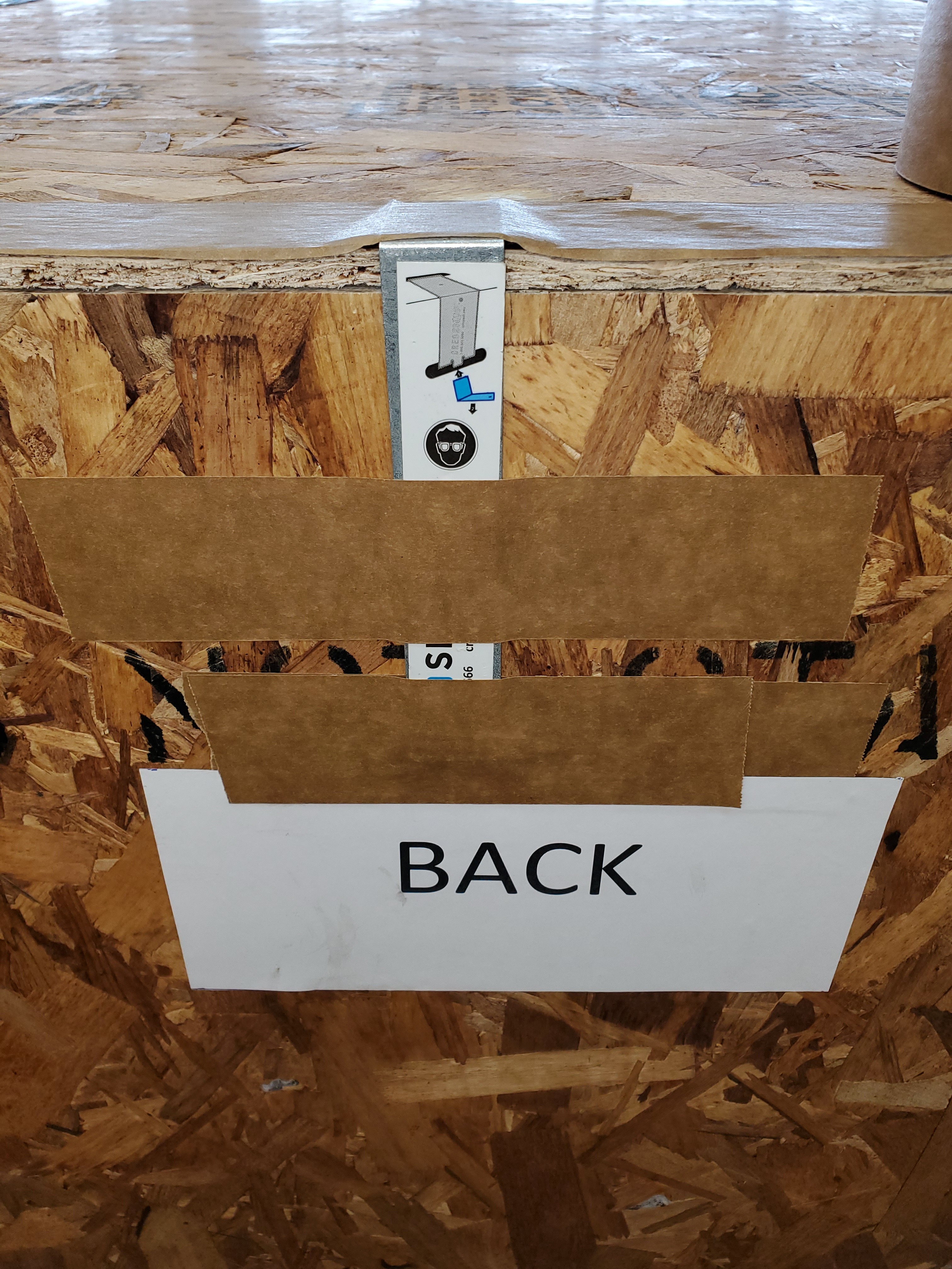
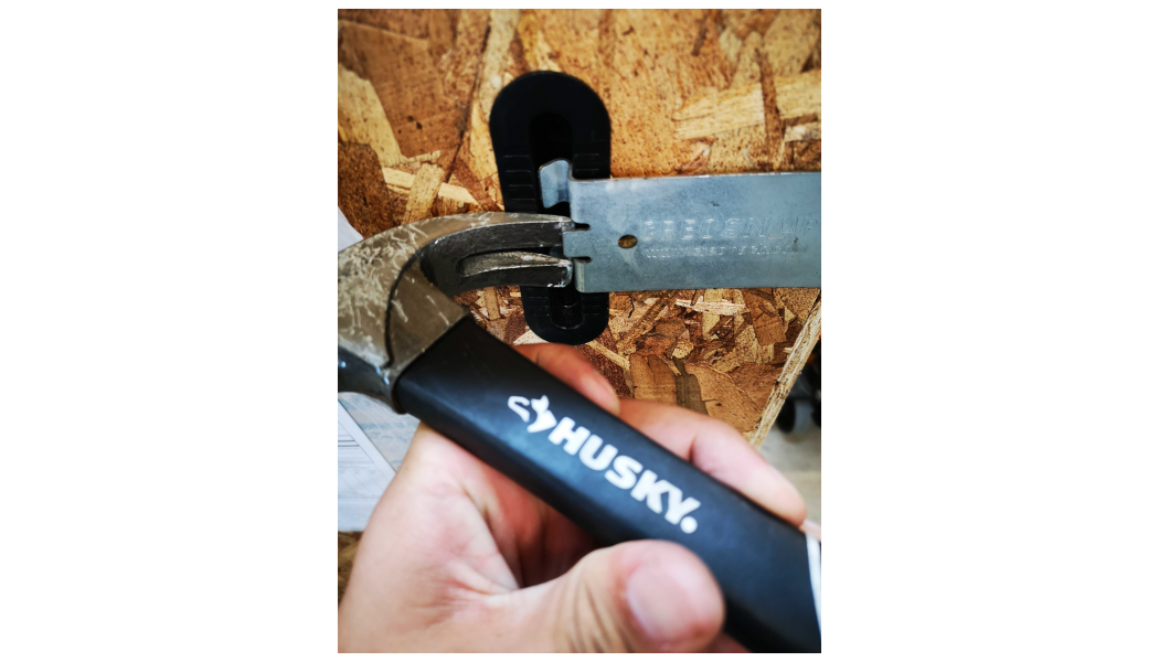
Remove the metal clip removal tool found on the rear panel of the crate.
Make sure unloading area is clear before the removal of the metal clips. The metal clips can fly away from the crate when removed. Failure to clear the work area can result in personal injury.
-
Remove the 28 metal clips and the five panels in the sequence that follows:
- Remove the eight metal clips that hold the top panel to the four side panels. Remove the top panel.
- Remove the eight metal clips that hold the rear panel to the right and left side panels and to the crate platform. Remove the rear panel.
- Remove the eight metal clips that hold the front panel to the right and left side panels and to the crate platform. Remove the front panel.
- Remove the two metal clips that hold the left side panel to the crate platform. Remove the left side panel.
- Remove the two metal clips that hold the right side panel to the crate platform. Remove the right side panel.
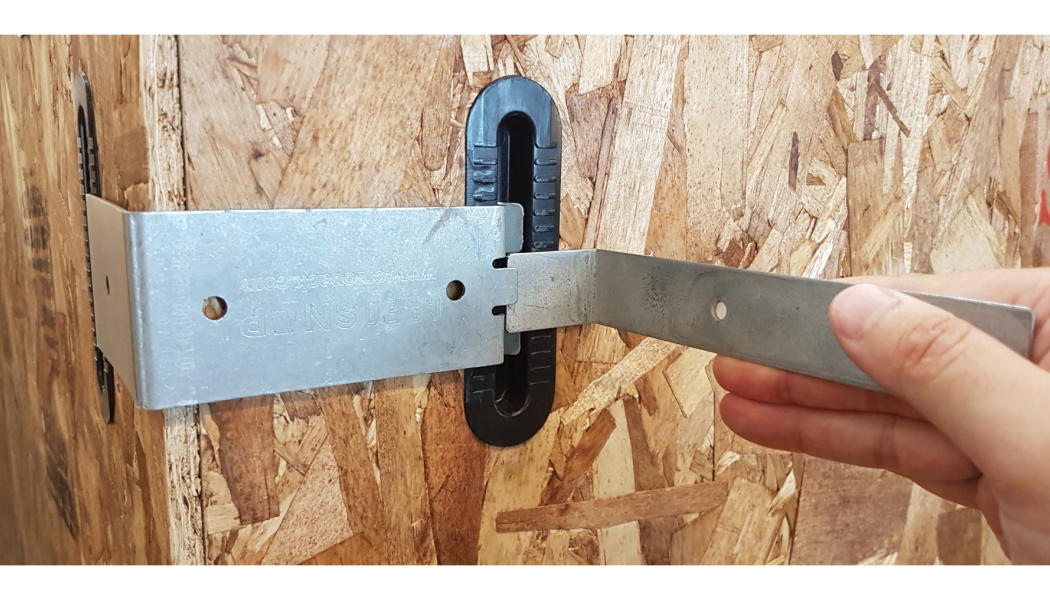
If the clip removal tool is not available, a claw hammer can be used to remove the clips.
Remove and Verify Shipped Items
- Remove the packing list found of the outside shipping crate panel.
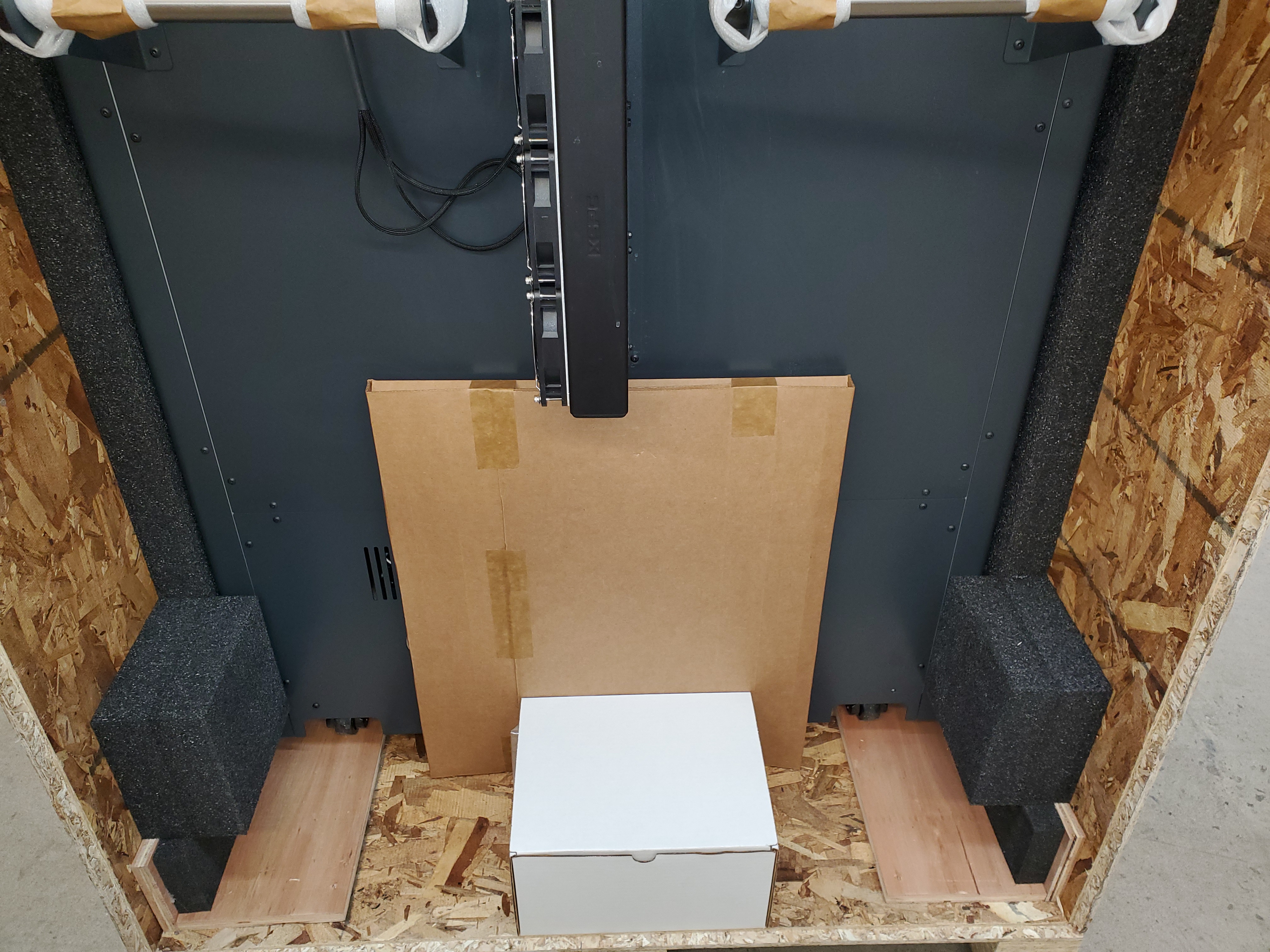
- Remove the component box found at the rear of the shipping crate platform.
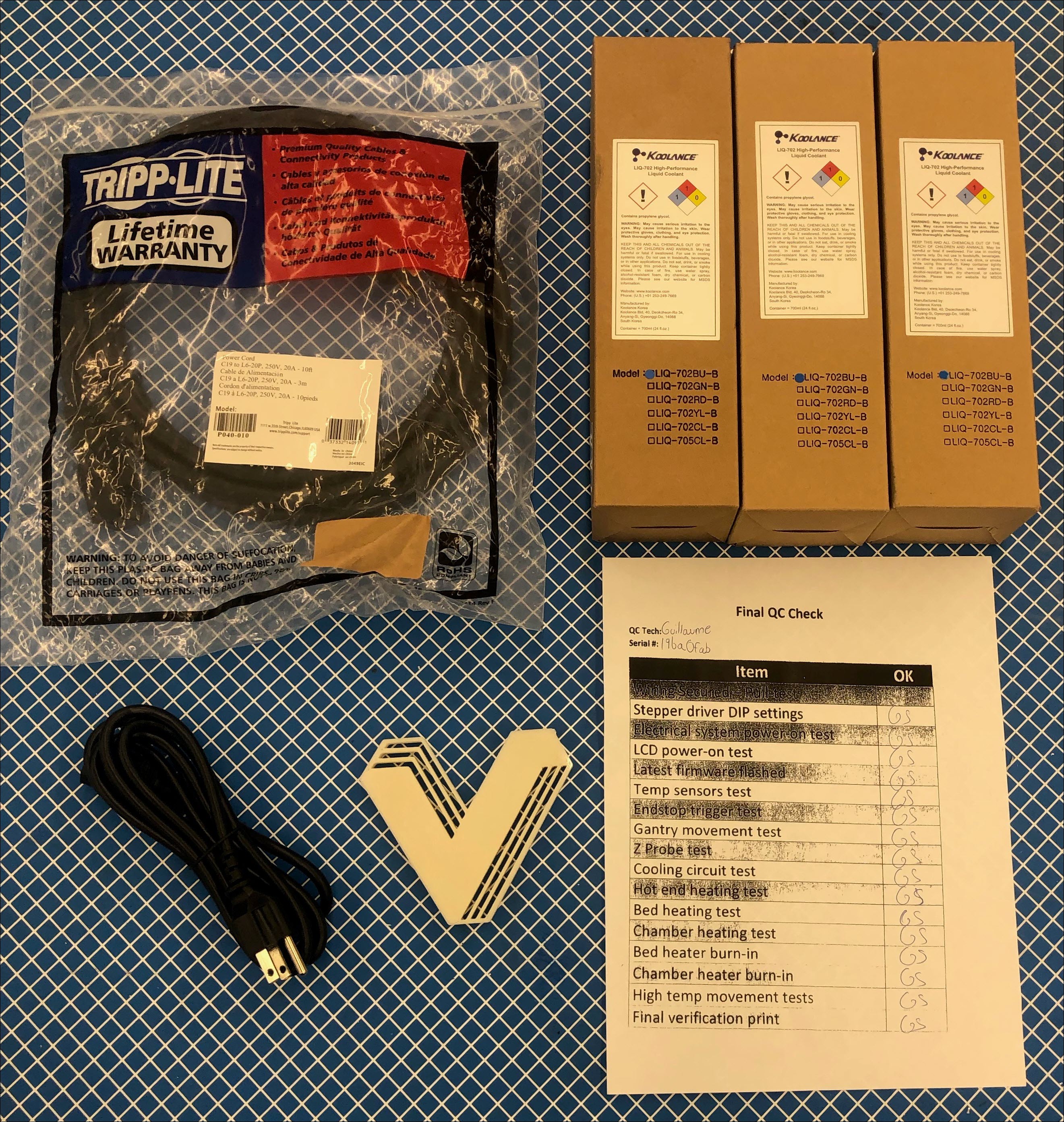
- Verify that the components that follow are included in the component box:
| Qty | Item | Description |
|---|---|---|
| 1 | Check List | Quality Assurance |
| 1 | Test Print | Quality Assurance |
| 1 | Power Cord, Machine | 10 FT NEMA L6-20P to Manual Reset In-Line GFCI to IEC60320 C19 20A 240V Power Cord (AON M2+, AON-M2 2020, AON-M2) |
| 1 | Power Cord, Vacuum Pump | 10 FT Power Cord, 10A, 18AWG, IEC-320-C13 to NEMA 5-15P (AON M2+) |
| 3 | Coolant | High-Performance Liquid Coolant, 700ml |
If additional parts were ordered with the AON3D machine, make sure that all the parts are included on the packing list and in the components box.
Reach out to our Customer Success team at help@aon3d.com if there are any damaged or missing parts.
Remove Machine from the Crate
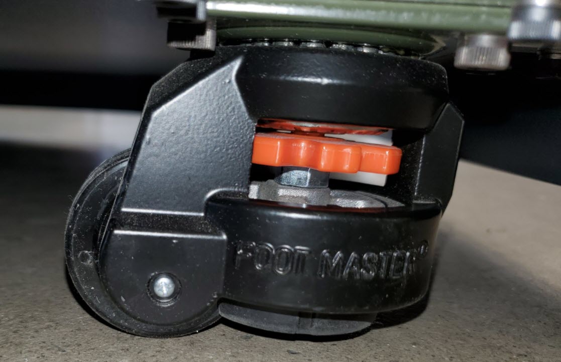
- Turn the orange level nut clockwise on the two rear caster wheels to unlock the caster wheels.
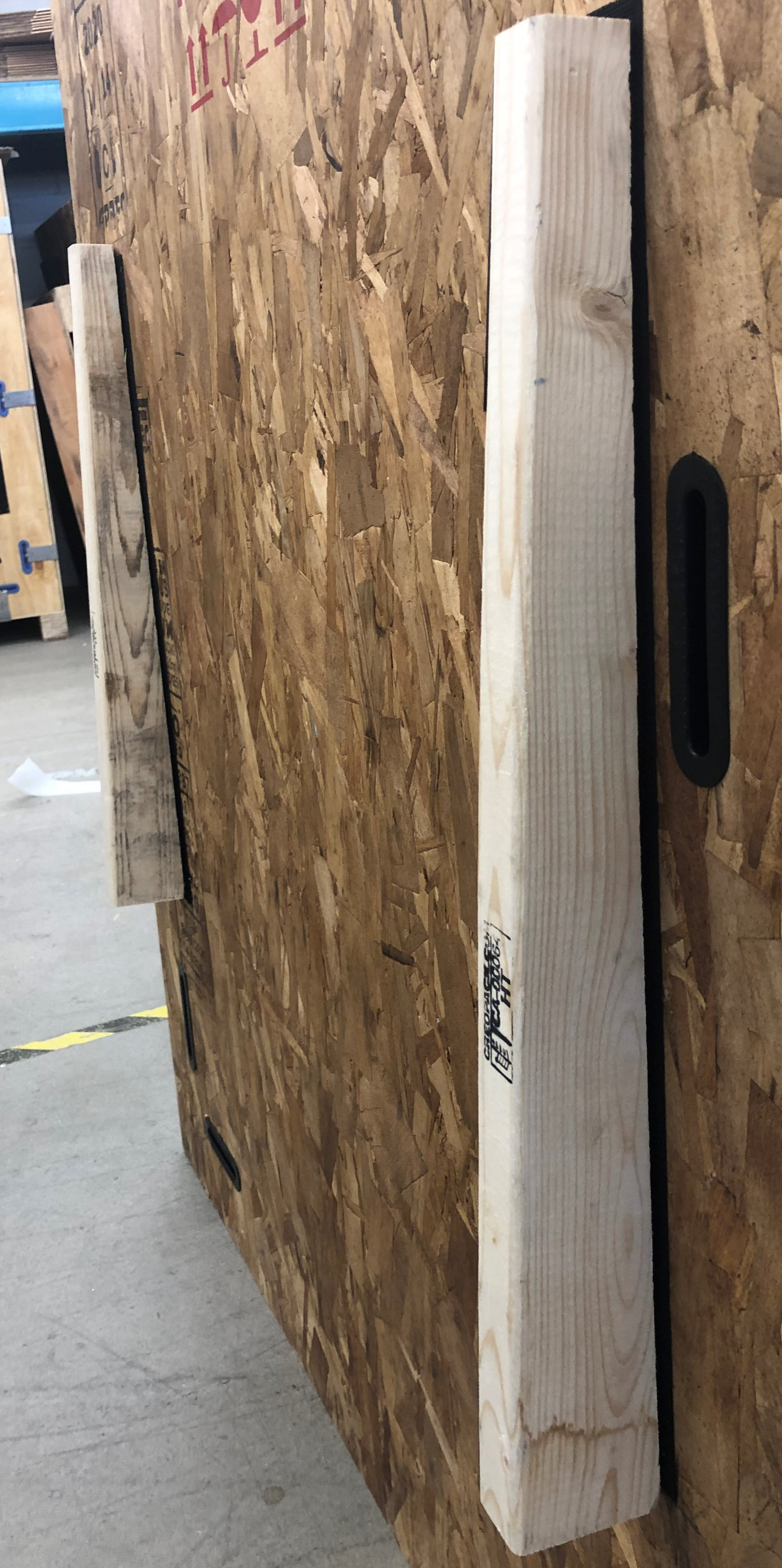
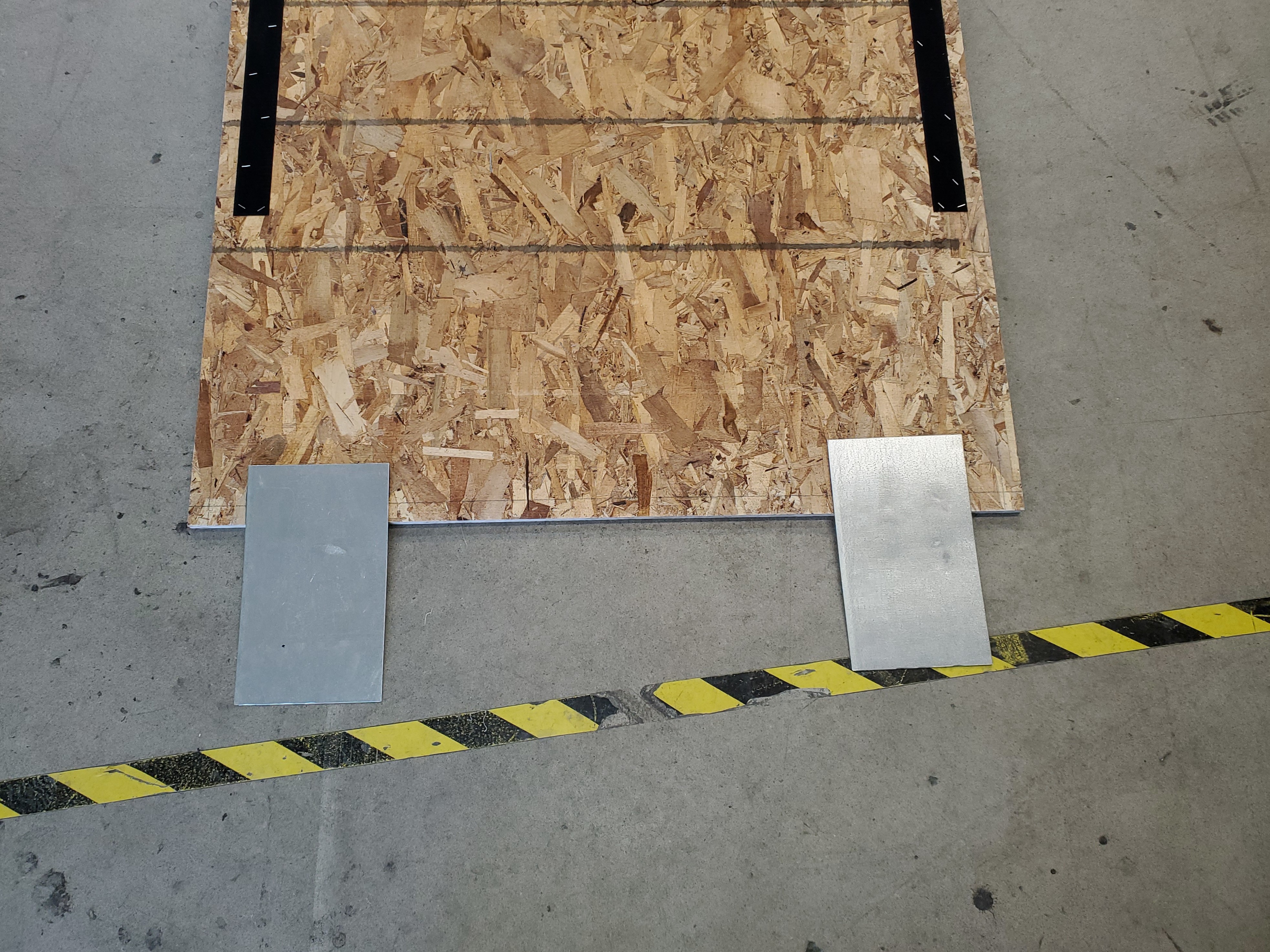
- Remove the two wooden triangular-shaped support blocks and the two metal ramp strips that are found on the rear panel.
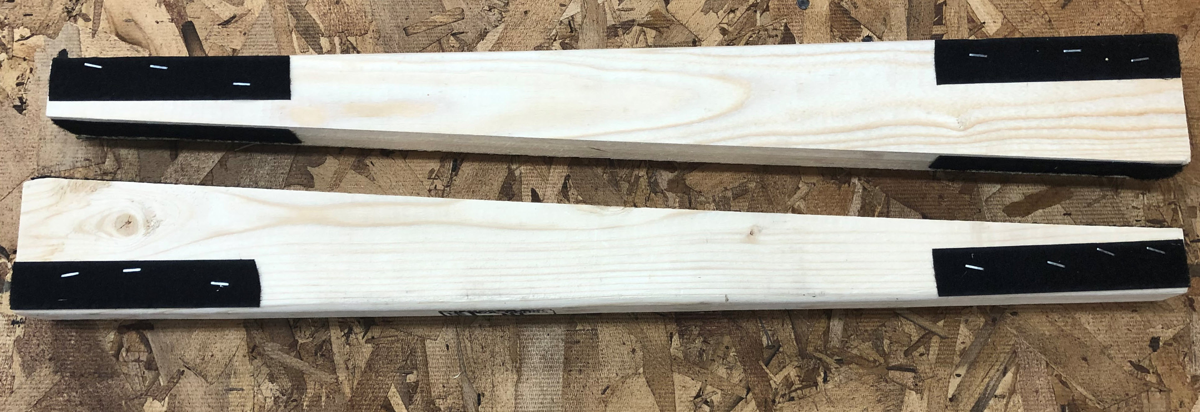
- Install the two wooden triangular-shaped support blocks onto the outer rear panel.
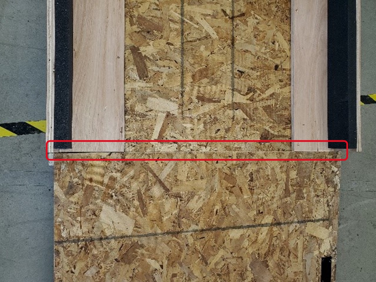
- Carefully put the ramp on the floor and onto the edge of the crate platform. Make sure the gap between the crate platform and the ramp is minimal.
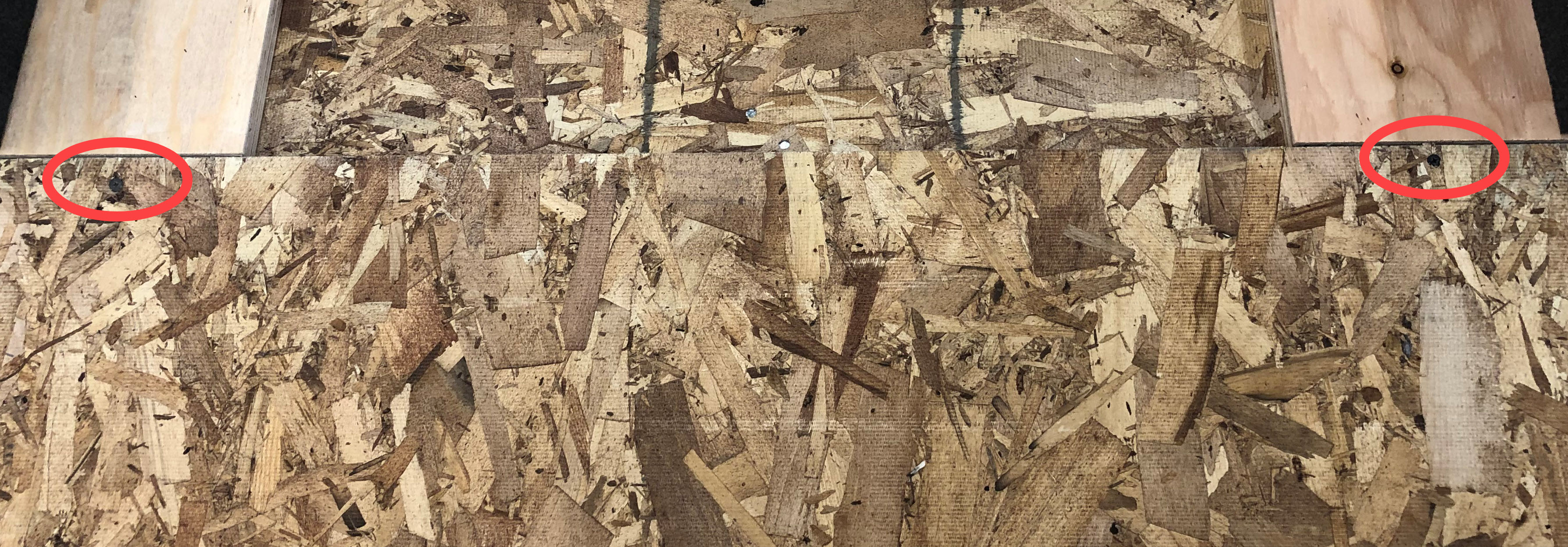
- Use the screwdriver to install two wood screws through the ramp, and into the crate platform.
- Install the two metal strips onto the end of the ramp.
Always use a minimum of two persons for the procedure that follows. The crated machine weighs in excess of 350 kg (770 lbs.) and can cause injury, and/or damage equipment, if control is lost when the machine is moved.
- Carefully move the machine over the ramp and onto the floor.
- Move the machine to its designated work location.
Level the Machine
The machine must be leveled before it can be connected and powered ON. Failure to level the machine correctly can cause damage to machine component(s), which will void the AON3D warranty.
If a spirit level is not available, an app for your smartphone can be used.
Open the Door
Level the X-Axis
- Open the build chamber door.
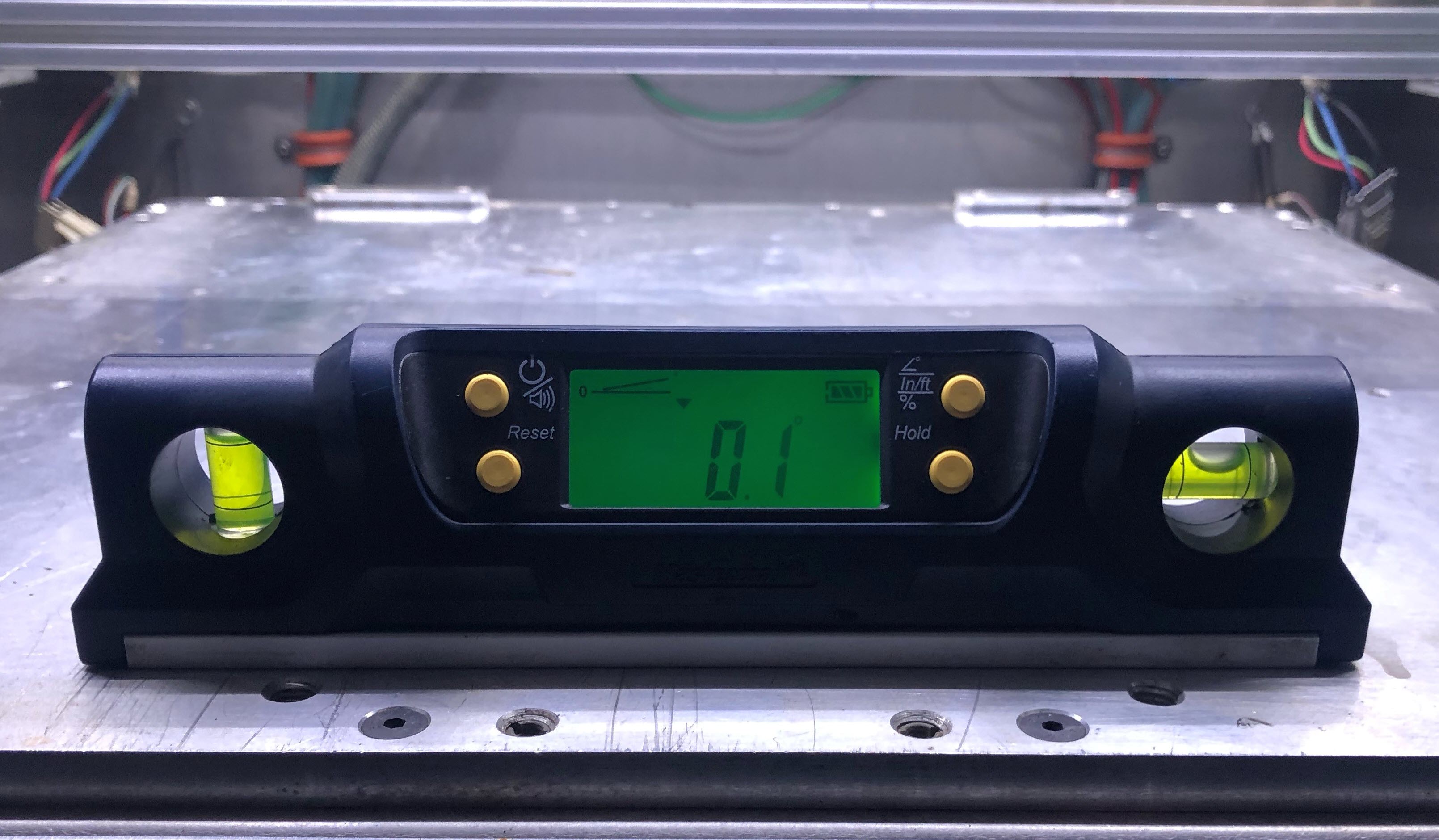
- Put the spirit level across the center of the bed, along the X-axis.
- Turn the individual orange caster nuts, in small increments, to level the machine along the X-axis.
- Do step 3, as necessary.
Level the Y-Axis
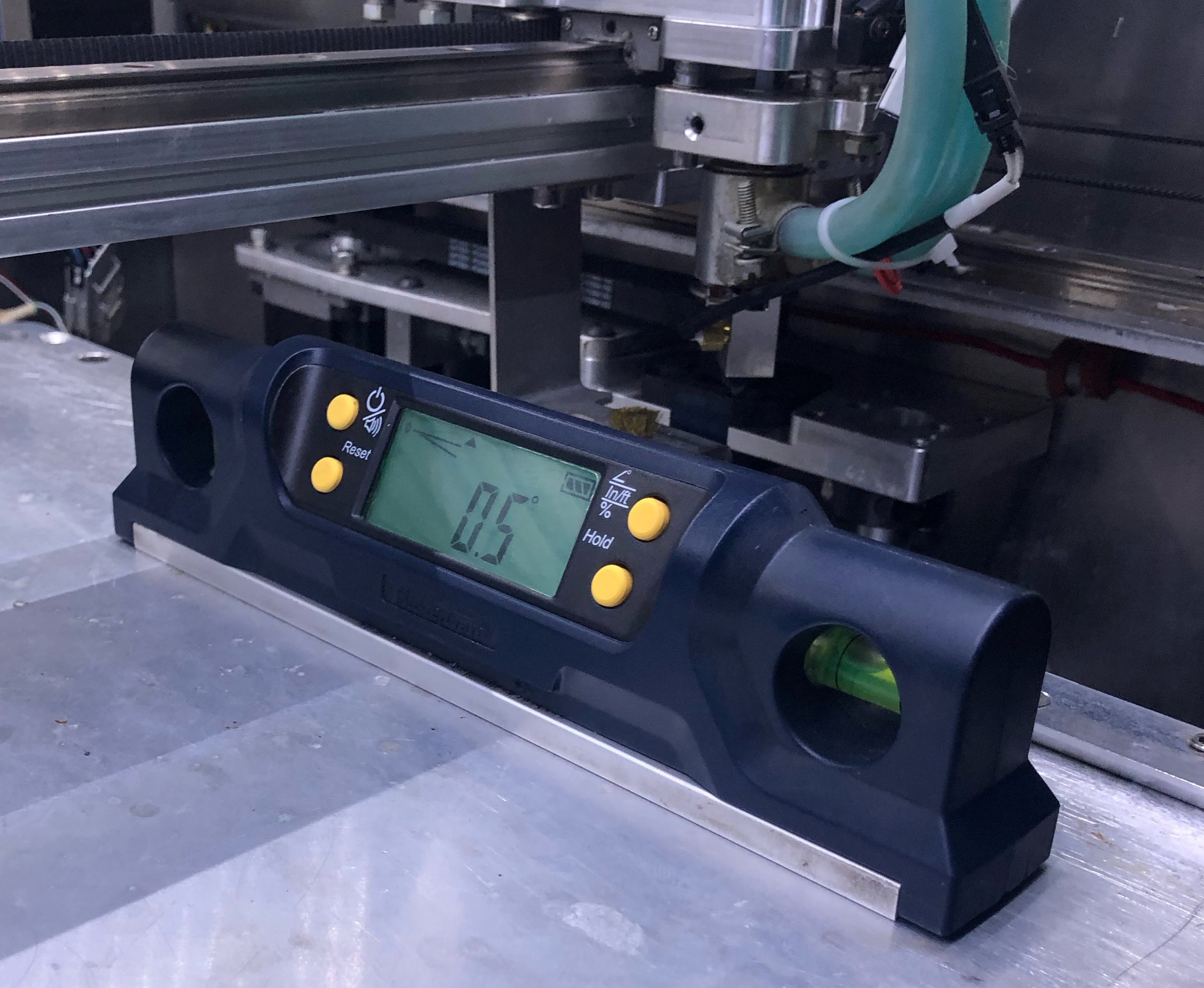
- Put the spirit level across the center of the bed, along the Y-axis.
- Turn the individual orange caster nuts, in small increments, to level the machine along the Y-axis.
- Do step 2, as necessary.
- Make sure that the X-axis is in level after the Y-axis has been leveled.
- Remove the spirit level from the build chamber.
- Remove all the shipping materials from the inside and outside of the machine. All packaging foam must be removed from the two toolheads, the X-axis gantry, and the two spool holders.
Put the Vacuum Pump on the Floor
The vacuum pump is mounted to the machine for ease of movement and shipping. It must be removed from the machine before printing.
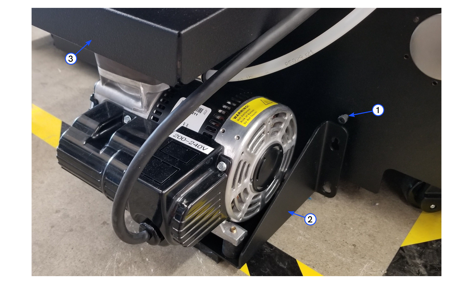
- Use the 4 mm hex key to loosen the four screws (1).
- Lift the vacuum pump assembly (2) from the machine and put it on the floor.
- Make sure that the pump is under the awning (3).
Keep the crate assembly and its packaging accessories, for at least 90 days after the machine has been received. In the case of a warranty claim, use the crate to ship the machine back to us for repair. This is necessary for AON3D to honor the warranty. After the 90 days, make sure to correctly dispose of the packaging materials in accordance with local laws and/or regulations.