Z Offset Calibration
| Model | [ ] AON M2+ (CE) | [ ] AON M2+ (R-NZ) | [ ] AON M2+ | [•] AON-M2 2020 | [•] AON-M2 |
| Category | [ ] Preventive | [ ] Corrective | [•] Calibration |
Summary
The procedure that follows gives instructions on how to calibrate the Z-axis on the AON-M2 and AON M2-2020 machines.
Estimated time: 30 minutes
The instructions that follow are for the AON-M2 and AON M2-2020 machines only.
Refer to Z Offset Calibration (M2+ Klipper) AON M2+ (CE), AON M2+ (R-NZ) and AON M2+ machines that have the Klipper-based firmware.
Refer to Z Offset Calibration (M2+ Marlin) AON M2+ (CE), AON M2+ (R-NZ) and AON M2+ machines that have the Marlin-based firmware.
Tools
None required.
Parts Information
None required.
Personal Protective Equipment
| Qty | Description | Minimum Specification |
|---|---|---|
| 1 | Safety Eyewear | ANSI/ISEA Z87.1 |
Procedural Index
Software Requirements
The instructions that follow shows the improvements added in software application v21.12.06.18.00.
Use the Graphical User Interface (GUI)/web browser to confirm the software version that is installed on your AON-M2 and AON-M2 2020:
- Select Settings > Updates.
If your machine does not have the latest software version, refer to the Software Update procedure.
Preheat Build Chamber Components
Make sure that there are no prints on the build surface. Remove print(s) before the procedure that follows is started. Failure to do so can cause a collision and cause damage to the machine component(s).
- Install the correct build plate. Refer to Install Build Plate.
- Preheat all the build chamber components to the recommended temperatures before a print is started. Make sure to obey the time necessary for all machine components to gradually increase to the recommended temperature. Refer to Preheat Build Chamber Components.
- On the GUI/web browser, select Temp.
- Input the correct bed (
B) and build chamber (T2) target print temperatures. Refer to Heat Build Chamber Components to select the recommended temperatures.
The wait time for build chamber components to increase to a stable temperature is one to four hours. Refer to Heat Build Chamber Components for the recommended list of time necessary for material that is to be printed. It is necessary to wait for the full recommended time to get the build chamber components to a stable temperature. Do not use the target temperatures, found on the GUI/web browser, to measure the temperatures in the build chamber during this procedure.
Filament Retraction
Machine components are hot at this point. Persons are recommended to wear the correct personal protective equipment to prevent injuries.
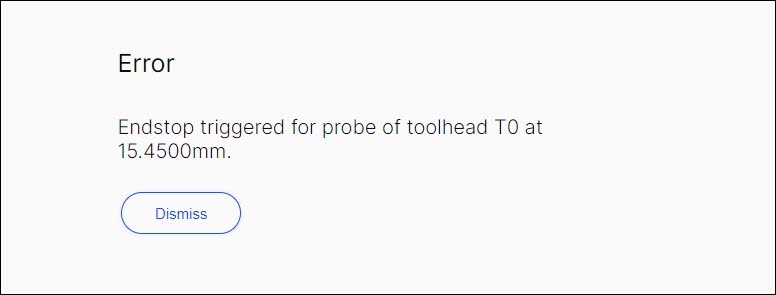
Filament must be retracted from the hot end assembly(ies) before a mesh is probed. Failure to retract the filament can cause damage to the hot end(s) and/or the probe assembly(ies), and can give incorrect Z-probe calibration results. If filament is not retracted, the GUI can notify the user with an error message.
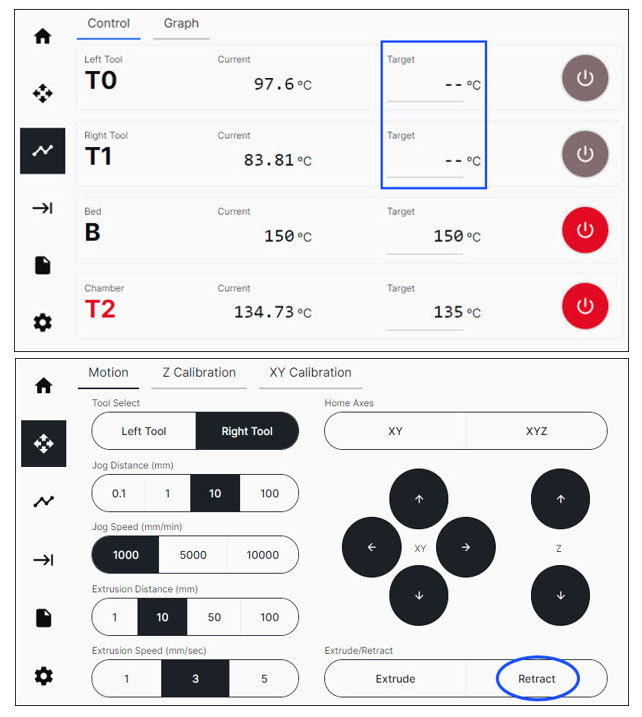
Use the GUI/web browser to retract the filament as follows:
- Select Temp, and input the toolhead(s) target temperature necessary.
- Let the toolhead(s) get to the target print temperature(s).
- Select Control > Motion.
- Under Tool Select, select
Left ToolorRight Tool. - Under the Extrusion Distance (mm), select
10. - Under the Extrusion Speed (mm/sec), select
3. - Select the Retract button two times to retract 20 mm of filament.
- Do steps 4 and 7 for the adjacent toolhead, if necessary.
Nozzle Temperatures
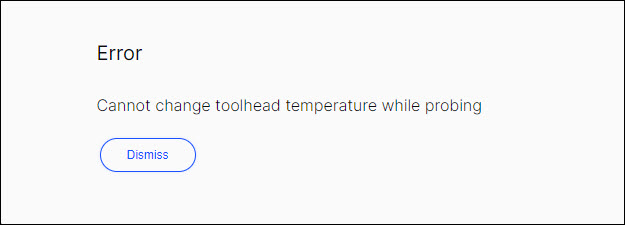
The selected toolhead target temperature must be ±10°C (±50°F) from the bed target temperature when a mesh is probed. The software will not let the machine probe the mesh if the toolhead(s) temperature(s) is(are) set incorrectly.
- On the GUI/web browser, select Temp.
- Input the toolhead(s) target temperature(s) to ±10°C (±50°F) of the target bed temperature.
- Let the toolhead(s) get to the target print temperature.
The toolhead(s) temperature(s) cannot be changed when the mesh probe sequence is in progress. The GUI/web browser will notify the user if the temperature is changed when the mesh probe sequence is in progress.
Probe a Mesh
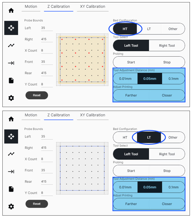
On the GUI/web browser, select Control > Z Calibration. On this menu, the user can do the actions that follow:
- Select the necessary Bed Configuration.
- Customize Probe Bounds and Probe Counts, if necessary.
- Adjust Z offset(s).
- Send command to start and stop the probe sequence.
Select Bed Configuration
Select the Bed Configuration that is installed in the machine.
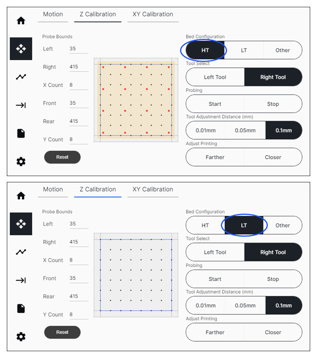
Set the Probe Bounds
The default grid can be resized to probe a smaller print area, if necessary.
The mesh uses different color points which are as follows:
- Black points represent the probe points.
- Red points represent the position of the screws on the AON3D High Temperature Build Plate.
- Blue perimeter represents the boundaries of the defined probe area.
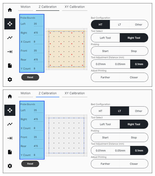
Restrictions on Probe Bounds are as follows:
| Probe Bound | Default Value | Minimum | Maximum |
|---|---|---|---|
| Left | 35 | 5 | Right - 30 |
| Right | 415 | Left + 30 | 445 |
| X Count | 8 | 3 | 10 |
| Front | 35 | 5 | Rear - 30 |
| Rear | 415 | Front + 30 | 445 |
| Y Count | 8 | 3 | 10 |
To reset the Probe Bounds to factory default values, select Reset.
Installing the AON-M2 High Temperature Build Plate into Simplify3D® only applies to Simplify3D® V4.
To install the AON-M2 High Temperature Build Plate into AON-M2 High Temperature Build Plate into Simplify3D® V4, refer to Slicer Setup.
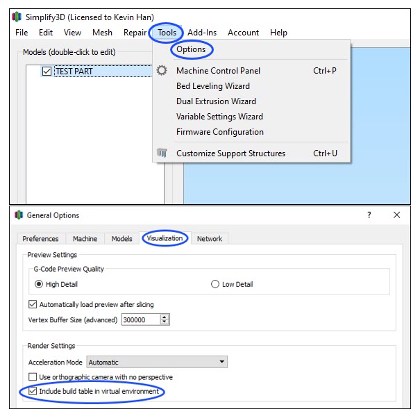
Use the instructions that follow to enable the build plate in the Simplify3D® environment:
- Open the Simplify3D® software.
- In the top toolbar, select Tools > Options.
- When a new window opens, select Visualization.
- Under Render Settings, select Include build plate in virtual environment.
- Select OK to close the window.
- Enter the Simplify3D® limit values in the Probe Bounds (Left/Right and Front/Rear) using the UI/web browser. The numerical value is the distance in millimeters relative to the (0,0) origin found at the front left corner of the build platform. The probe area must be a minimum of 30 mm x 30 mm.
- The preview will update automatically to show the new print area selected.
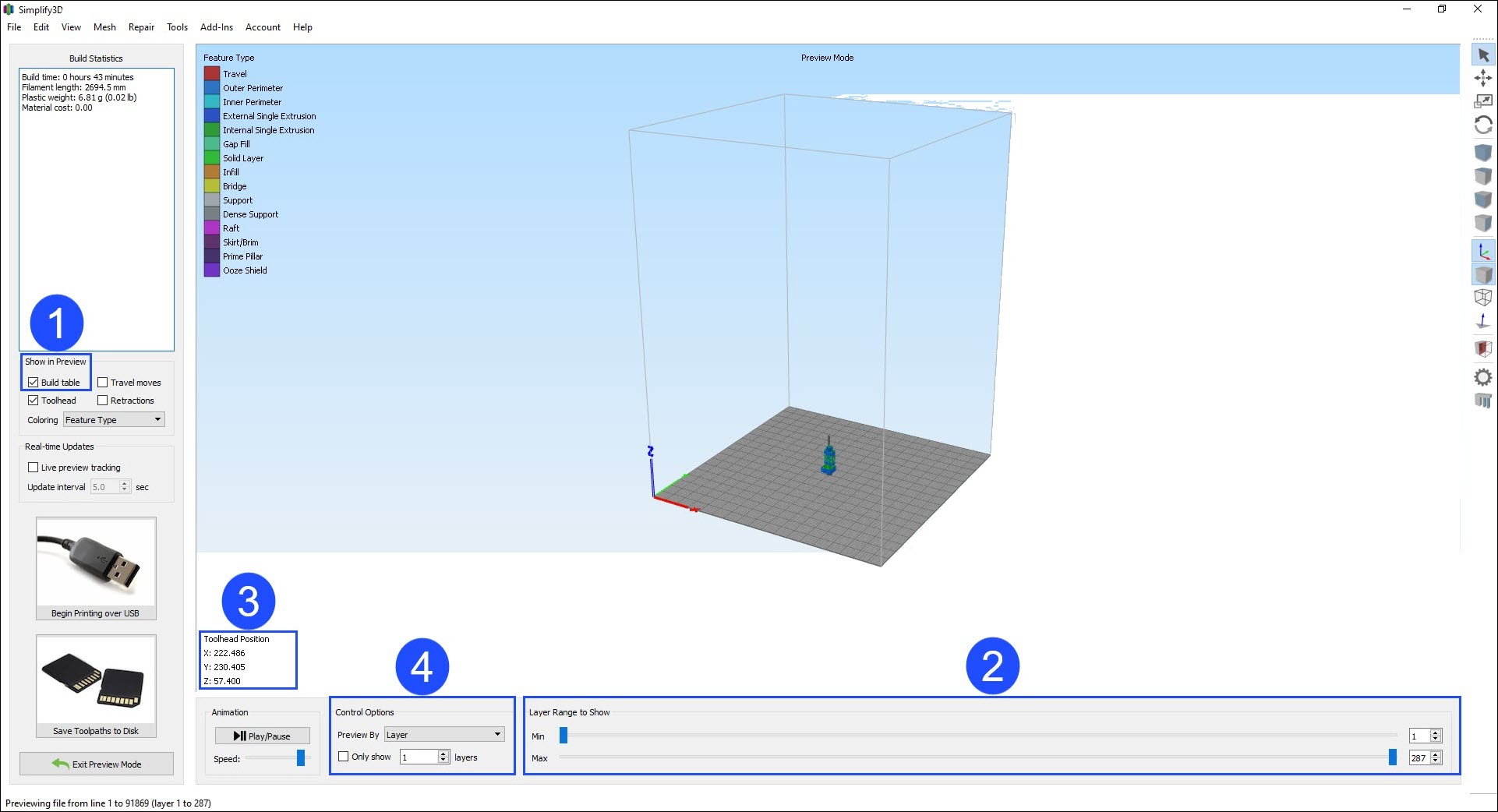
To reset the Probe Bounds to factory default values, select Reset.
Set the Probe Counts
The X and Y probe counts are the number of equally distanced points, along the X and Y axes, that are used to build the probe grid. The user can edit the number of X and Y probe counts, if necessary.
- The maximum amount of probe counts is 100 points (10 along the X-axis and 10 along the Y-axis).
- The minimum amount of probe counts is nine points (three along the X-axis and three along the Y-axis).
A higher Probe Count will add more definition to a grid, but a longer quantity of time is necessary to do the mesh probe procedure. A lower Probe Count will decrease the time necessary to probe a mesh, but will give less definition than a Probe Count with a higher numerical value.
To help the user plan the probe sequence, the coordinates of key points on the build platform are as follows:
- The blue perimeter represents the outline of the print area of the AON-M2 Aluminum Build Plate.
- The interior of the blue perimeter is the PEI plate outline, and screws, found on the AON-M2 High Temperature Build Plate.
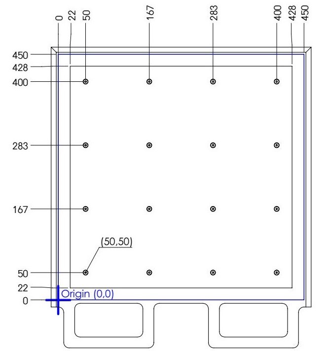
Do not probe the external area of the default bounds. This can cause the bed to collide into the toolhead(s). The default grid will probe around the bed screw heads that hold the PEI plate to the aluminum bed base.
Do not use Probe Bounds that will probe directly onto the AON-M2 High Temperature Build Plate screw heads. This can cause error(s) in the mesh.
Probe the Build Platform
AON3D recommends that the build platform be probed before every print. Probe the build platform, calibrate the Z-axis, and/or adjust the Z offset, when:
- The machine is moved and/or leveled.
- There is a change of ±20°C (±68°F) in component temperature(s).
- There is a change of build platform.
- Heater block assembly adjustments, removal, maintenance and/or repair occur.
- Hot end adjustments, removal, maintenance and/or repair occur.
The two toolheads Z-axes must be calibrated when the two toolheads are in operation for the same print.
- Make sure that the build platform is clean and free of unwanted materials.
- Select Control > Z Calibration.
- Under Tool Select, select
Left ToolorRight Toolto be calibrated. - Under Probing, select Start to start the probe sequence for the selected toolhead.
- The machine will automatically home all axes, and then start to probe the build platform.
• If the probe assembly does not compress, or gets stuck in the compressed state, select Stop to cancel the probe sequence. This can also trigger a Z probe triggered prior to probing error notification on the UI/web browser. Make sure that the filament has been correctly retracted from the hot end(s). Refer to Retract the Filament.
• Each point on the grid will be measured five times during one probe sequence.
• The selected toolhead will move to the center of the X-axis, and to front of the Y-axis, of the probe grid.
• The nozzle will move very near to, or possibly, touch the build platform, after the probe sequence is completed. - After the build platform has been probed, select Tool Adjustment Distance, and select
0.1mmor0.05mmincrement. - Under Adjust Printing, select
FartherorCloserto adjust the distance between the build platform and the nozzle.- Select Farther to move the build platform down (away from the nozzle).
- Select Closer to move the build platform up (toward the nozzle).
Make sure to give the Z-axis the time necessary to move in the selected direction.
Make sure the probe is not compressed at this point. This can occur if the Z offset is set too near to the build platform. To prevent toolhead collision(s) onto the build platform, keep a small distance between the nozzle and build platform.
- Make sure that the nozzle does not touch the build platform. If the nozzle touches the build platform, select
0.1mm, then selectFartheruntil there is a distance between the nozzle and the build platform. - Select the
FartherandCloserbuttons to adjust the Z offset until the nozzle is approximately 0.1 mm from the bed platform. - Do steps 3 to 9 for the adjacent toolhead.
• Do not home XYZ after the probe sequence has been completed. If the Z-axis is homed, it can cause the mesh to move and give incorrect results in calibration. Use the jog function to move the toolhead(s).
• To stop the probe sequence, select Stop at any point to cancel the procedure. This stops the probe sequence, and the active toolhead returns to the home position. If the sequence is stopped when the toolhead is in motion to the home position, the toolhead will stop. Home XYZ after toolhead(s) is(are) stopped.
• All probe values are reset to the default configuration of 30 mm when a probe sequence is stopped. In the UI/web browser, select Terminal and input M-code M501 to get the values from the last correct probe sequence.
Before a Print is Started
X/Y Toolhead Offset Calibration
If a print uses the two toolheads for the same print, the two toolheads must be calibrated along the X/Y-axes before a print is started. The X/Y-axes calibration procedure adjusts the coordinate system of the two toolheads to be in line with each other. Refer to X/Y Toolheads Offsets Calibration.
Filament Extrusion
After the build surface has been probed, filament must be extruded from the hot end(s) before a print can begin.
- Select Control > Home Axes, select
XYto park the two toolheads to each end of the X-axis. - Select Temp, and input the hot end target temperature necessary for the material used for the print.
- Let the selected toolhead(s) get to the target temperature(s).
- Select Control > Motion.
- Select Tool Select, then select
Left ToolorRight Toolto be used for the print. - Select
Extrudetwo times to extrude 20 mm of filament. - Do steps 2 to 6 for the adjacent toolhead, if necessary.

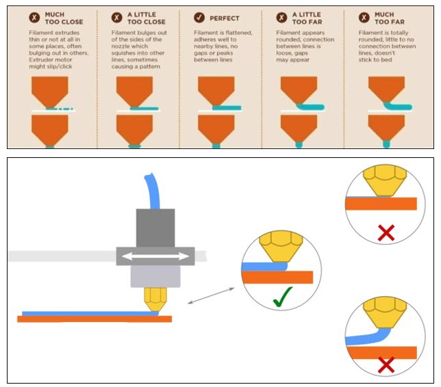
First Layer Print Calibration
The Z offset must be calibrated for the first layer. This can be done when a skirt, brim or raft is in progress.
- On the GUI/web browser, select Files > Print to start a print.
- Select the Control > Z Calibration.
- Select the
0.05 mmor0.01 mmincrement to adjust the Z offset. - Select the
FartherandCloserbuttons to adjust the Z offset height at the start of the print.- Make sure to give the machine the time necessary to register the command.
- Examine the layer and adjust the Z offset as necessary.
- Do steps 3 and 5 for the adjacent toolhead.
All Fused Filament Fabrication (FFF) Simplify3D® profiles provided by AON3D include brim(s), skirt(s), and/or raft(s) to help adjust the Z offset. Refer to the Material Guides section for more information. To manually add brims, skirts, and/or rafts, refer to Simplify3D® Additions tab.