Z Offset Calibration (M2+ Klipper)
| Model | [•] AON M2+ (CE) | [•] AON M2+ (R-NZ) | [•] AON M2+ | [ ] AON-M2 2020 | [ ] AON-M2 |
| Category | [ ] Preventive | [ ] Corrective | [•] Calibration |
Summary
The procedure that follows gives instructions on how to calibrate the Z-axis on the AON M2+ (CE), AON M2+ (R-NZ) and AON M2+ machines that have the Klipper-based firmware.
Estimated time: 30 minutes
The instructions that follow are for the AON M2+ (CE), AON M2+ (R-NZ) and AON M2+ machines that have the Klipper-based firmware only.
Refer to Z Offset Calibration (M2+ Marlin) AON M2+ (CE), AON M2+ (R-NZ) and AON M2+ machines that have the marlin-based firmware.
Refer to Z Offset Calibration for the AON-M2 and AON M2-2020 machines.
Tools
None required.
Parts Information
None required.
Personal Protective Equipment
| Qty | Description | Minimum Specification |
|---|---|---|
| 1 | Safety Eyewear | ANSI/ISEA Z87.1 |
Procedural Index
- Preheat Build Chamber Components
- Nozzle Temperatures
- Probe a Mesh
- Before a Print is Started
- First Layer Print Calibration
Preheat Build Chamber Components
Make sure that there are no prints on the build surface. Remove print(s) before the procedure that follows is started. Failure to do so can cause a collision and cause damage to the machine component(s).
- Open the build chamber door.
- Install the correct build sheet onto the vacuum chuck. Refer to Install Build Sheet.
- Close the build chamber door.
- Preheat all the build chamber components to the recommended temperatures before a print is started:
- On the GUI/web browser, select Temperatures.
- Input the correct
BedandChambertarget print temperatures. Make sure to obey the time necessary for all machine components to gradually increase to the recommended temperature. Refer to Preheat Build Chamber Components.
The wait time for build chamber components to increase to a stable temperature is thirty minutes to four hours. It is necessary to wait for the full recommended time to get the build chamber components to a stable temperature.
Nozzle Temperatures
The selected toolhead target temperature must be as close as possible as the extrusion temperature and within 50°C from the bed target temperature when a mesh is probed. The software will not let the machine probe the mesh if the toolhead temperature is set incorrectly.
- On the GUI/web browser, select Temperatures.
- Input the toolhead(s) target temperature(s) as close as possible as the extrusion temperature and within 50°C from the bed target temperature.
- Let the toolhead(s) get to the selected temperature.
Probe a Mesh
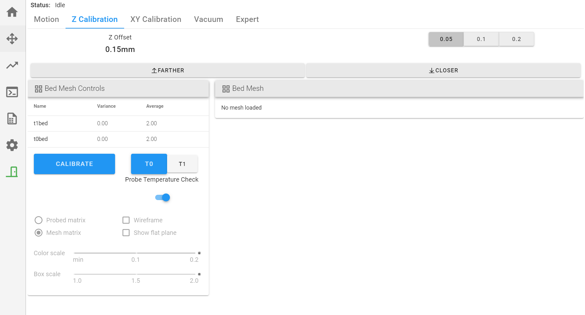
On the GUI/web browser, select Control > Z Calibration. On this menu, the user can do the actions that follow:
- Adjust Z offset(s).
- Send command to start and stop the probe sequence.
Probe the Build Platform
AON3D recommends that the build surface be probed before every print. Probe the build platform, calibrate the Z-axis height, and/or adjust the Z offset, when:
- The machine is moved and/or leveled.
- There is a change of ±20°C in component temperature(s).
- There is a change of build platform.
- Heater block assembly adjustments, removal, maintenance and/or repair occur.
- Hot end adjustments, removal, maintenance and/or repair occur.
The two toolheads Z-axes must be calibrated when the two toolheads are in operation for the same print.
- Make sure that the build platform is clean and free of unwanted materials.
- Select Control > Z Calibration.
- Select
T0orT1to be calibrated. - Select
CALIBRATEto start the probe sequence for the selected toolhead. - The machine will automatically home all axes, and then start to probe the build platform.
• The selected toolhead will move to the center of the X-axis and Y-axis of the probe grid.
• The nozzle will move very near to, or possibly, touch the build platform, after the probe sequence is completed. - Do steps 3 to 5 for the adjacent toolhead.
Before a Print is Started
X/Y Toolhead Offset Calibration
If a print uses the two toolheads for the same print, the two toolheads must be calibrated along the X/Y-axes before a print is started. The X/Y-axes calibration procedure adjusts the coordinate system of the two toolheads to be in line with each other. Refer to X/Y Toolheads Offsets Calibration.
Filament Extrusion
After the build surface has been probed, filament must be extruded from the hot end(s) before a print can begin.
- Select Control > Motion, select
⌂to park the two toolheads in the X and Y axes. - Select the Temperatures, and input the hot end target temperature necessary for the material used for the print.
- Select the
T0orT1to be used for the print. - Let the selected toolhead(s) get to the target temperature.
- Select Control > Motion
- Select
20as Extrude Length (mm) thenExtrudeto extrude 20 mm of filament. - Do steps 2 to 6 for the adjacent toolhead, if necessary.
First Layer Print Calibration
The Z offset must be calibrated for the first layer. This can be done when a skirt, brim or raft is in progress.
- On the GUI/web browser, select Files > Print to start a print.
- Select the Control > Z Calibration.
- Select the
0.05,0.01or0.2increment to adjust the Z offset. - Select the
FartherandCloserbuttons to adjust the Z offset height at the start of the print.- Make sure to give the machine the time necessary to register the command.
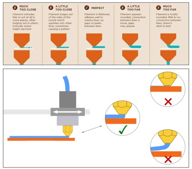
- Examine the layer and adjust the Z offset as necessary.
- Do steps 3 and 5 for the adjacent toolhead.
All Fused Filament Fabrication (FFF) profiles provided by AON3D include brim(s), skirt(s), and/or raft(s) to help adjust the Z offset. Refer to the Material Guides section for more information. To manually add brims, skirts, and/or rafts, refer to Simplify3D® Additions tab.