Print Settings

In the configuration AON3D provides standard print settings that cover the most common print conditions. This module is where the user is required to make most modifications depending on model geometry and part application requirements. This page covers the most common and critical settings available on SuperSlicer to optimize prints.
Printer Settings includes all the hardware-related settings that are specific to the printer. These settings include nozzle size, build volume, extruder capabilities, machine limits, acceleration and feed rates, and the firmware. Most of the settings under this tab require No Change by the user, as they are set by AON3D team according to the AON M2+ specifications. However, there are some settings that the user will be able to modify and change as they see fit according to model and print requirements. This document covers the settings that are most common to modify or that the user could change as per their requirements.
The top left of the window contains a drop-down menu, from where the user can select the T0 and T1 nozzle sizes. Similar to the drop-down on the left panel on the main UI. Always make sure to have the same selection on both the UI and the individual tab. They may not necessarily be identical.
Once the desired nozzle size combination is selected, the tabs under Printer Settings will update to AON3D standard presets. Click on each tab to see the setting options. Below are the settings that may require modifications on a more common basis.
Perimeters & Shell
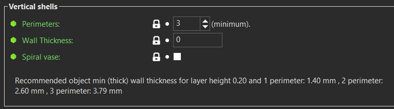
Perimeters: The default value for perimeters is 3. This sets the number of outlines which are printed for a given layer. This value is a minimum and may be increased for sloping perimeters for improved quality.
Wall thickness: This value should not be changed. If it is changed, the extrusion width needs to be set to a value where an integer value for perimeters is possible.
Spiral vase: This enables vase mode which will print only a single perimeter with automatic layer height for a given model, without solid layers or infill.
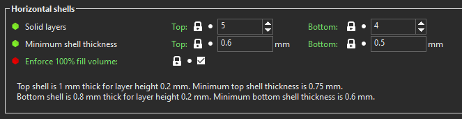
Solid layers: This value changes the number of fully filled layers for the Top and Bottom of the model.
Minimum shell thickness: This value creates a lower bound for the total thickness for the Top and Bottom layers. This is especially useful when adaptive layer height is on to prevent thin top layers which can cause pillowing.
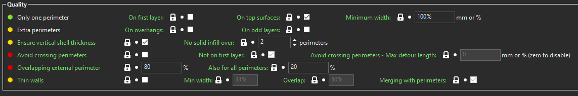
Only one perimeter: This forces a single perimeter on either the first layer or all top layers. This can improve the appearance of the surfaces.
Extra perimeters: This enables extra perimeters on overhangs or on alternating layers. The computation which adds extra for the overhanging regions is fairly heavy and will slow slicing times.
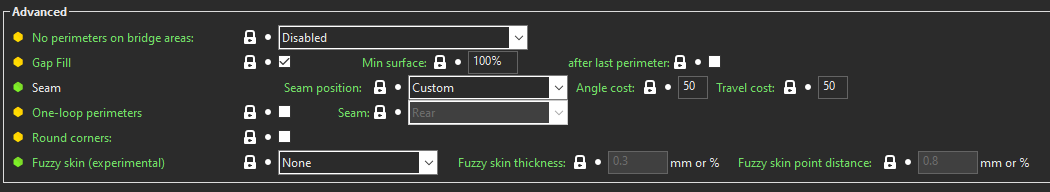
Gap fill: Calculates areas where a single extrusion can be used to fill an area that cannot fit a perimeter or infill.
Seam: This automatically moves the retractions of the outer perimeters to create a specific position for the seam. Choose from any of the presets in the drop-down, or you can create a custom positioning by manipulating the cost functions:
- Angle cost will penalize any surface that is flat (higher value moves the seams to corners).
- Travel cost will penalize extra travel to accommodate the custom seam position (lower value here allows the seam more freedom but may increase print time).
Slicing
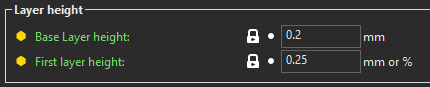
Base layer height: This value sets the Z height for each layer of the print. These values are preset for a given Print Setting profile. Increasing this value reduces outer surface quality of the perimeters as the beads will be rounder (more visible layer lines). Decreasing this value can improve the surface quality, but can cause beads to be compressed too much which can also make surface quality worse (overextrusion).
First layer height: This value sets a different Z height for the first layer of a print to help with first layer adhesion and/or surface quality. It is usually slightly larger than the Base layer height by default.
Infill
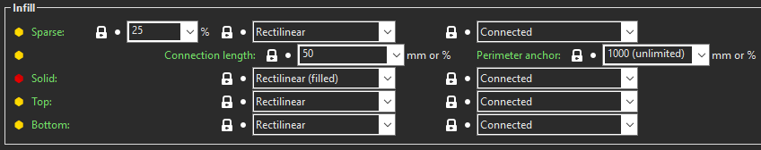
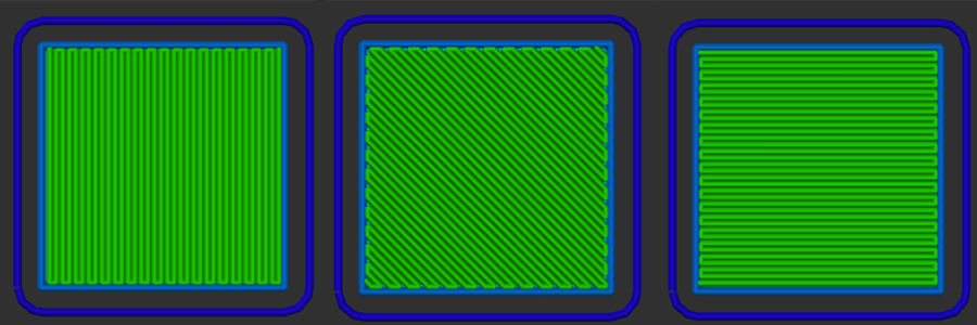
Sparse: The first value indicates the amount of fill for the part (in %). The subsequent drop-down allows the user to choose the pattern for the sparse fill. AON3D recommends Rectilinear or Gyroid by default, but different patterns suit different geometries.
Solid: The user can choose the pattern for all solid layers that are not the outermost top or bottom layers. AON3D recommends Rectilinear or Monotonic. Concentric may be useful if the model is circular in the XY plane.
Top & Bottom: The user can choose the pattern for the outermost top and bottom layers. AON3D recommends Rectilinear, Monotonic, or Concentric for similar reasons as Solid Infill.
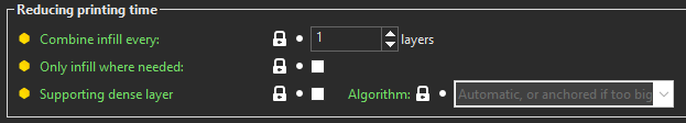
Combine infill every: This value will change how often infill is printed on a per-layer basis. If this value is set to 2 layers the infill will only print every other layer at double the Base layer height. AON3D does not recommend a value higher than 2 for best results.
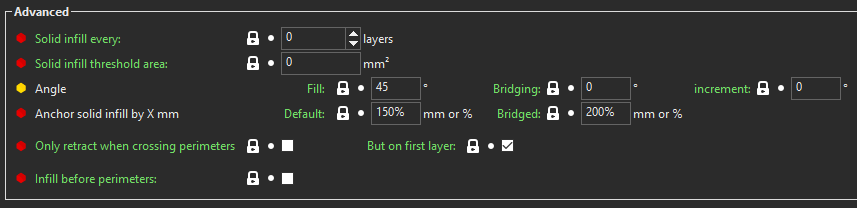
Angle: This value sets the angle at which the infill is printed, this primarily applies to Rectilinear or Monotonic at 0°, 45° and 90°:
Skirt & Brim
 Skirts are usually used to check Z calibration and nozzle flow, and can be increased to as many as needed.
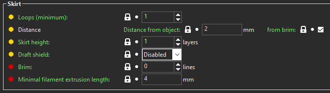
Loops: This value sets the number of perimeters for the Skirt which outlines the model.
Distance: This value sets how far the Skirt is from the model (or a Brim if enabled), it is set to 2 [mm] by default.
 Brims are used to help with first layer adhesion and to prevent warping, downsides include extra print time and poor edges on first layers.
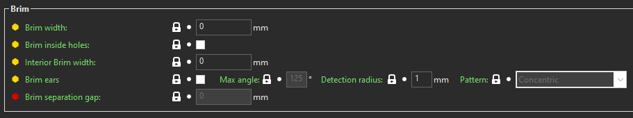
Brim width: This value sets how large to make the Brim surrounding the first layer of the model (in [mm] not perimeters).
Support material
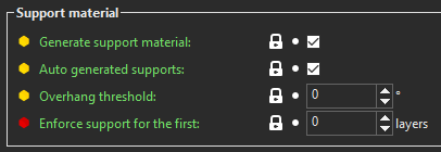
Generate support material: This needs to be checked to enable supports.
Auto-generate support material: This will enable supports to be automatically generated without the need to use support enforcers or paint-on supports.
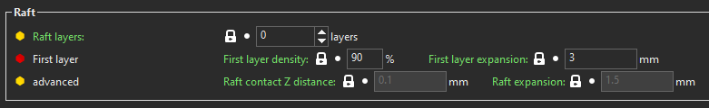
Raft layers: This value sets the number of layers that will be under the raft which will be printed as a support structure. Set to a value above 0 to enable a raft.
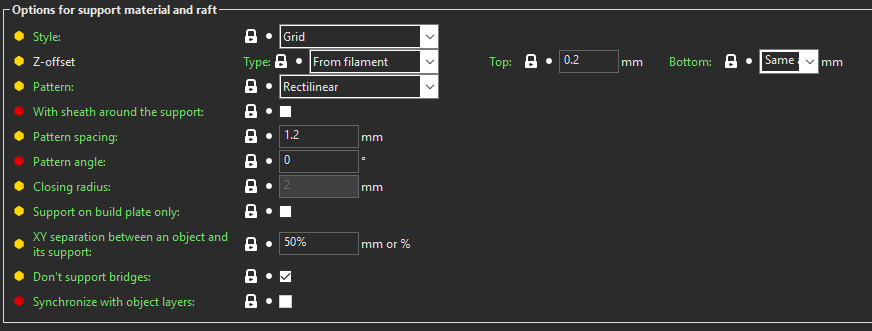
Style: There are two options for the style of support structures. Grid is a more traditional support generation which creates pillar-like objects to fill the area which. Snug only generates support directly under the designated area to support.
Z-offset: This value indicates the separation distance from the support and the model. In Type we recommend using From filament unless a soluble support solution like AquaSys® 120 or 180 is used. In that case, select None (soluble). The Top and Bottom are to manipulate the gap in [mm] from the model to the top and bottom of the support structure respectively. These values are normally the same and should be less than one layer height, usually in the range of 0-0.2mm depending on adhesion between materials.
Pattern: The user can choose the pattern for the support structure. By default Rectilinear is recommended, but Rectilinear grid and Honeycomb are also useful for different geometries.
With sheath around support: This enables one perimeter to be printed around the support structure. This helps with stability for printing, but it increases print time and makes the material harder to breakaway or dissolve.
Pattern spacing: This value sets the gap between the beads of the generated support and is analogous to Sparse infill, though this is in [mm] not (%).
Pattern angle: This value sets the angle at which the support is generated and is analogous to Infill angle.
Closing radius: This value is only used when the Style is set to Snug. This parameter will fill in any gaps in support which are smaller than the indicated radius in [mm].
XY separation: This value sets the gap between the model and the support in the XY plane. This can be in [mm] or (%) of nozzle diameter. AON3D recommends 0-0.3mm or 50% of nozzle size depending on geometry.
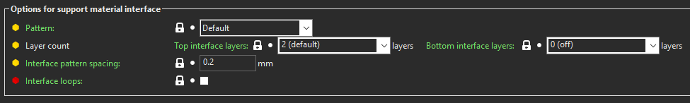
Pattern: The user can choose the pattern for the interface layers. Default automatically switches between Rectilinear and Concentric. Monotonic can help with some tool path or temperature consistency. Concentric is best for circular geometries.
Layer count: These values indicate the number of interface layers between the support and model. Top interface layers and Bottom interface layers are to set the top and bottom respectively. AON3D recommends 2-4 layers but it depends on the Pattern spacing and bridging capabilities of materials.
Interface pattern spacing: This value in [mm] sets the gaps between the beads in the interface layers. AON3D recommends this value to be in the range of 0-0.2mm.
Speed
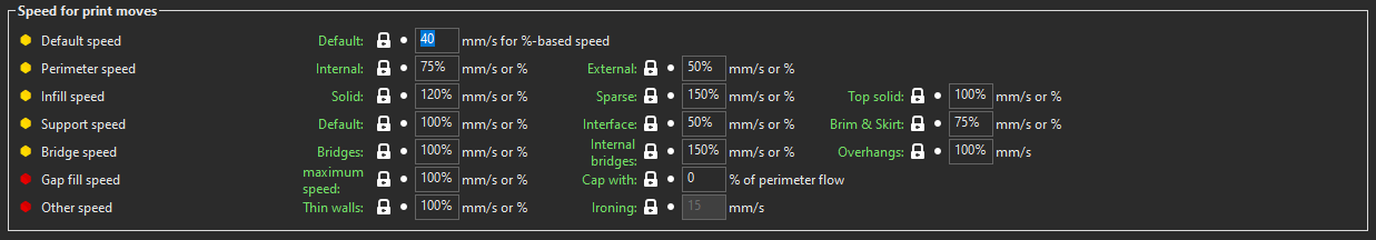
Speed for print moves is what sets how fast the parts are printed. They can be set as either a set speed in [mm/s] or a percentage (%). These settings have been tuned for the AON M2+ and should not be heavily modified.
Default: This speed is shown in [mm/s] and is what sets the percentage base changes for all other settings. If the speed needs to be changed this is where it should be done.
Others: All the other speed options are in percentage form so that they can be scaled and modified accordingly with the set speed. This could be changed to get fast print times if some print quality is not a priority. For example External perimeter is at 50% of the default speed to give a clean print surface but if not needed this can be increased to get faster print times. The settings have been tuned to get the nicest results but this can be tuned for other outcomes.

First layer speed: This setting is used to increase first layer adhesion by slowing down the nozzle, this speed is set independently of the default speed and is shown in [mm/s].
Small perimeter speed: This setting slows down the print based on short perimeters to reduce over heating. The Speed is set as either [mm/s] or (%) based on the default print speed. Then a Min and Max length to dictate where this speed applies, this can also be set as a [mm] or (%) of nozzle diameter.
Width & Flow
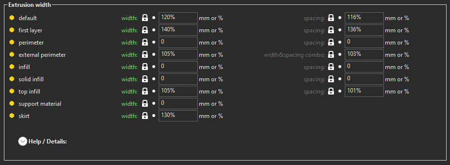
These settings work as percentage of the nozzle size. These have been optimized based on AON3D’s validated materials and should not be changed.
Default: This will be the base width if nothing else is set.
First layer: This is usually slightly larger to help with adhesion.
External perimeter: This is slightly undersized to get cleaner walls.
Multiple extruders
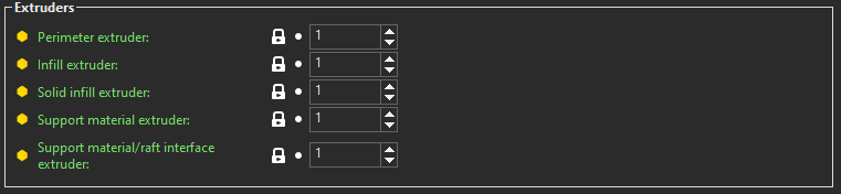
Allows the user to set which features use which extruder. The AON M2+ has 2 extruders so do not go above 2. This is pre-configured for different support options, generally the support material is on T1 or extruder 2 in this section.
Output option
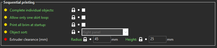
This setting is for multiple objects on the bed and which features should be printed individually.
Complete individual objects: This enables this setting.
Print all brim at startup: This can be turned enabled to increase bed adhesion.
Extruder clearance: This is set by AON3D and should not be changed.
A short description of each setting on SuperSlicer is available by hovering the cursor over the setting name. To learn more, PrusaSlicer’s documentation contains useful pages on specific slicer settings.
Basic slicing support is available to all AON3D customers. For advanced support inquiries, an AON3D success plan may be required. Our Success plans help businesses get started fast, minimize downtime, and quickly become experts in industrial additive manufacturing.
Contact us at help@aon3d.com to get started or for Success Plan information.