Load Filament
| Model | [•] AON M2+ (CE) | [•] AON M2+ (R-NZ) | [•] AON M2+ | [•] AON-M2 2020 | [•] AON-M2 |
| Category | [•] Installation | [ ] Operation | [ ] Maintenance |
Summary
The procedure that follows gives instructions on how to load the filament through the feed path.
Estimated time: 30 minutes
Reach out to our Customer Success team at help@aon3d.com for genuine AON3D part(s) inquiries.
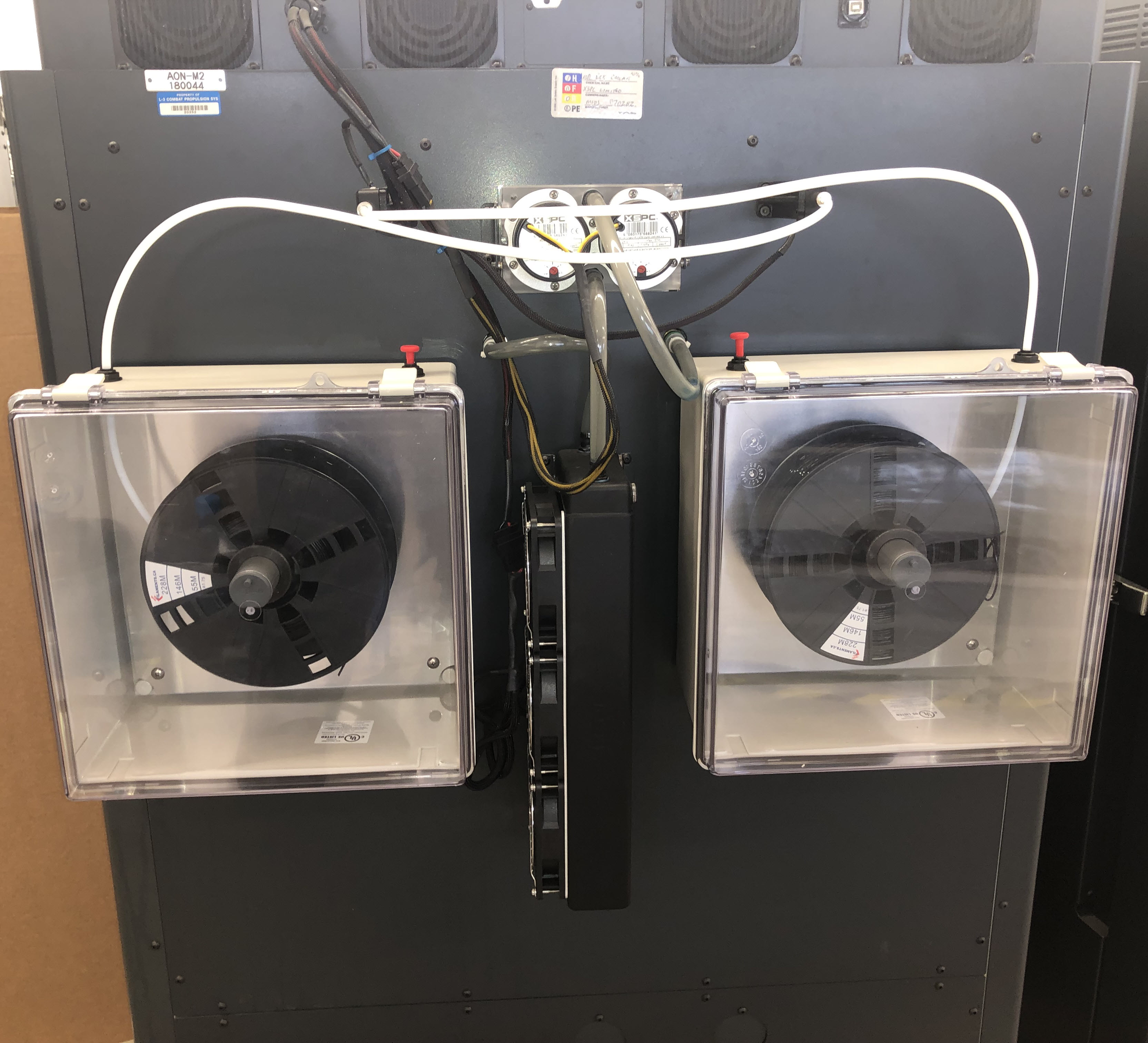
Two Filament Dry Storage and Feed Systems (dry boxes) can be installed on the all machine models. Refer to Replace Filament.
The AON M2+ includes the feed path upgrade kit (part number K-0999-012) as standard equipment.
AON3D offers a feed path upgrade kit (part number K-0999-012). The AON-M2 2020 Filament Feed Path Field Upgrade Kit:
•Helps lower the friction factor between the filament and the PTFE tube, which allows the material to be fed to the extruder with less restrictions.
•Increases the bending radii of the feed path, which reduces the risk of the filament breakage inside the feed tube.
Tools
| Qty | Description | Specification |
|---|---|---|
| 1 | Wire Cutters | N/A |
| 1 | Brush, Wire | Brass, soft bristle |
| 1 | Hex Key | 4 mm |
Parts Information
| Qty | Part Number | Description |
|---|---|---|
| A/R | Filament, Roll of | N/A |
Reach out to our Customer Success team at help@aon3d.com to purchase rolls of filament.
Personal Protective Equipment
| Qty | Description | Minimum Specification |
|---|---|---|
| 1 | Safety Eyewear | ANSI/ISEA Z87.1 |
| A/R | Nitrile Gloves | ISO 2859-1 or ASTM D6319 |
| A/R | Gloves | Work |
Prepare Filament
- Unpack the spool of filament.
- Remove the end of the filament from the spool.
Make sure that filament is unrolled from spool without tangles. Filament tangles will cause extruder(s) to jam, cause print failure, and/or cause damages to machine component(s).
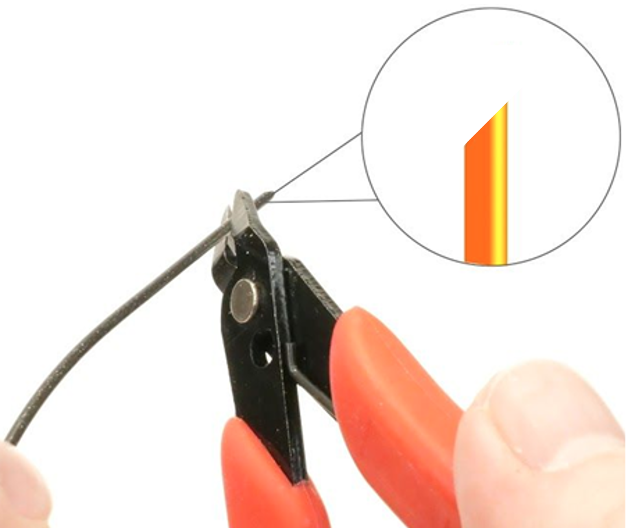
- Use the wire cutter to cut a 45-degree angle at the end of the filament.
Filament Dry Storage and Feed System Configuration
Filament spool limit dimensions are as follows:
• Largest outside diameter: 305 mm (12 in)
• Smallest inside diameter: 32 mm (1.25 in)
• Largest width: 110 mm (4.33 in).
AON3D recommends that two small desiccant pouches be installed in the dry box enclosure to prevent moisture.
Install the Roll of Filament for T0 Operation
When the machine is viewed from the rear, do the steps that follow:
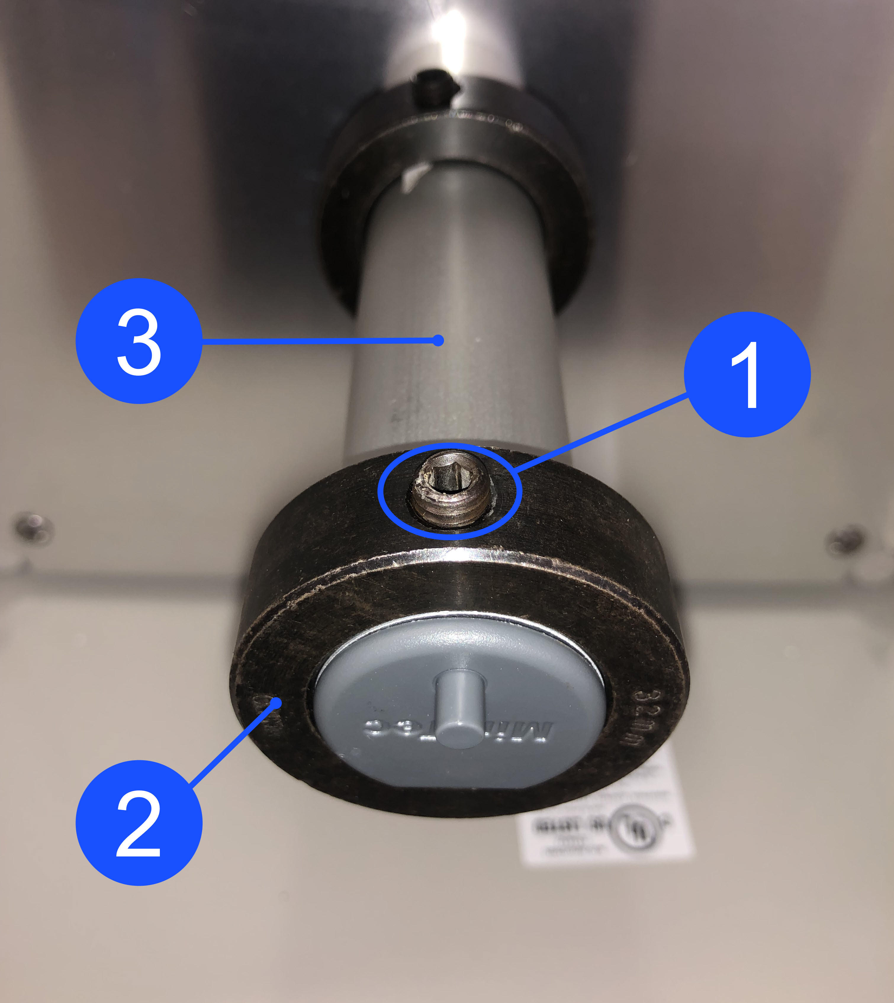
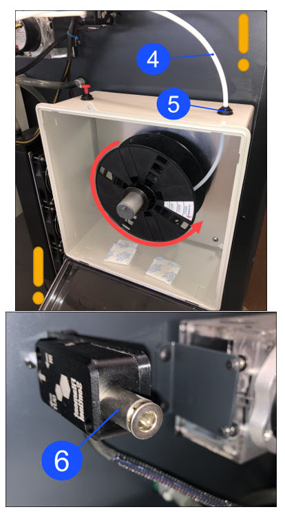
- Use the 4 mm hex key to loosen the spindle collar screw (1). Remove the spindle collar (2).
When the machine is viewed from the rear, the roll of filament must be installed as such that the filament unwinds CLOCKWISE into the internal 152 mm (6 in) feed tube. Failure to install the filament correctly into the feed tube can cause print failures and/or cause damage to machine component(s).
Make sure that filament is unrolled from the spool without tangles. Filament tangles will cause print failures and/or cause damage to machine component(s).
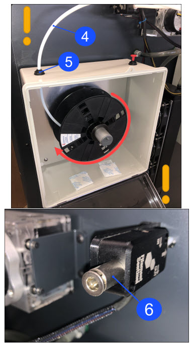
- Install the roll of filament onto the filament spindle (3). Push the roll of filament to the rear of the dry box. Make sure that the roll of filament is correctly installed.
- Install the the spindle collar (2) onto the filament spindle (3). Put the spindle collar (2) approximately 7 mm (one-quarter inch) away from the roll of filament.
- Use the 4 mm hex key to tighten the collar screw (1). Do not tighten too much.
- Put the end of the filament into the 152 mm (6 in) internal feed tube.
Install the Roll of Filament for T1 Operation
When the machine is viewed from the rear, do the steps that follow:
- Use the 4 mm hex key to loosen the spindle collar screw (1). Remove the spindle collar (2).
When the machine is viewed from the rear, the roll of filament must be installed as such that the filament unwinds COUNTERCLOCKWISE into the internal 152 mm (6 in) feed tube. Failure to install the filament correctly into the feed tube can cause print failures and/or cause damage to machine component(s).
Make sure that filament is unrolled from the spool without tangles. Filament tangles will cause print failures and/or cause damage to machine component(s).
- Install the roll of filament onto the filament spindle (3). Push the roll of filament to the rear of the dry box. Make sure that the roll of filament is correctly installed.
- Install the the spindle collar (2) onto the filament spindle (3). Put the spindle collar (2) approximately 7 mm (one-quarter inch) away from the roll of filament.
- Use the 4 mm hex key to tighten the collar screw (1). Do not tighten too much.
- Put the end of the filament into the 152 mm (6 in) internal feed tube.
Spool Holder Configuration
Make sure spool orientation is placed as such that the filament is looped and fed from behind of the spool when installed.
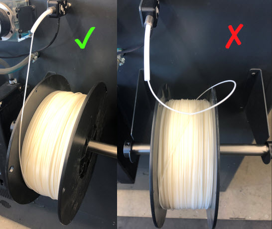
- Put the filament spool holder tube through the center hole of the filament roll.
- Put the filament roll onto the spool holder brackets found on the rear panel of the machine.
Put Filament in the Feed Path
All machine components are hot at this point. Persons are to wear the correct personal protective equipment to prevent injuries.
- Open build chamber door.
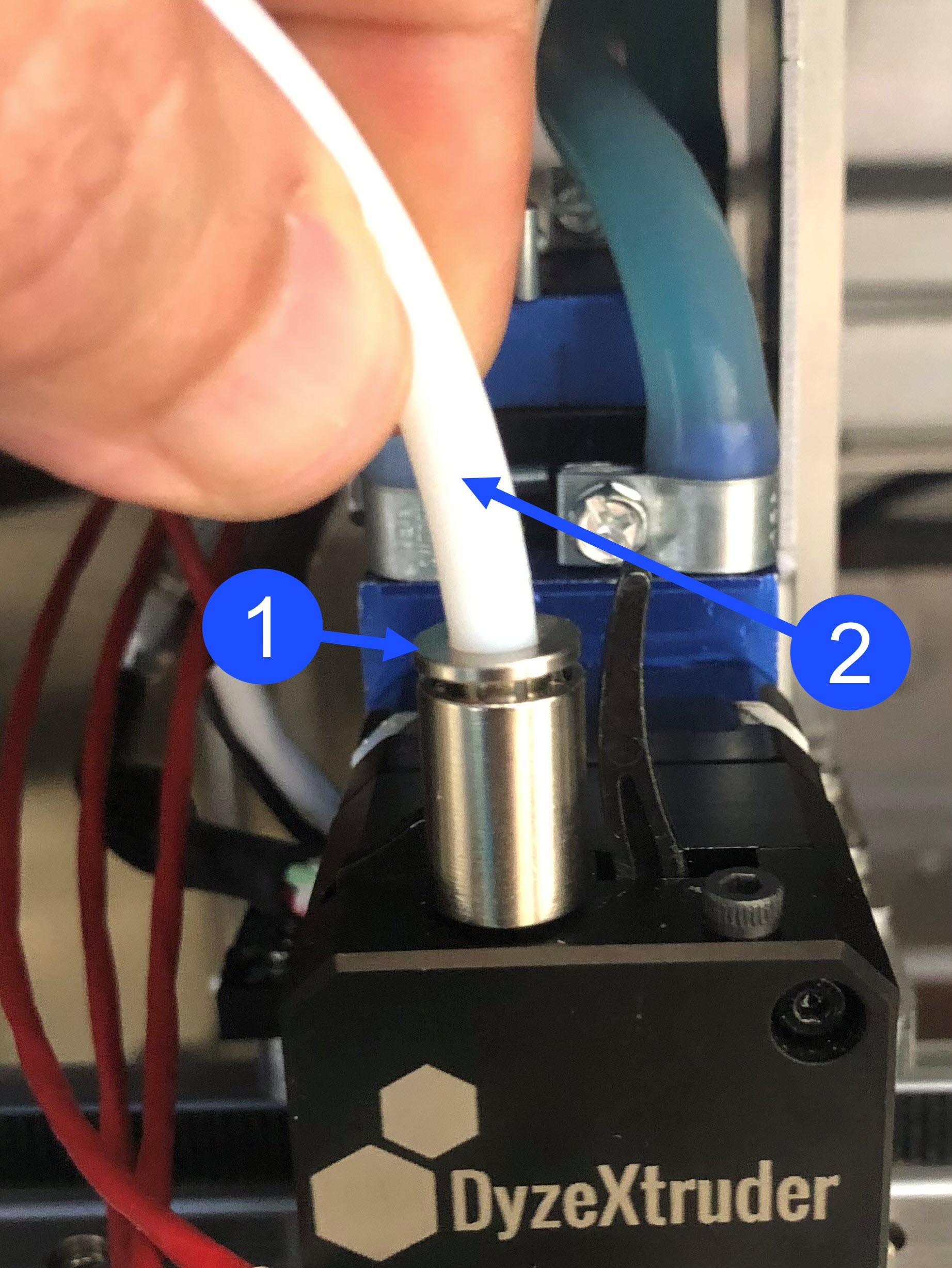
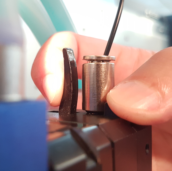
- Disconnect the PTFE tube (2) found at the top of the extruder body. Press down on the fitting (1) with one hand and carefully pull out the PTFE tube (2) with the other hand.
- Insert the filament through the filament detector.
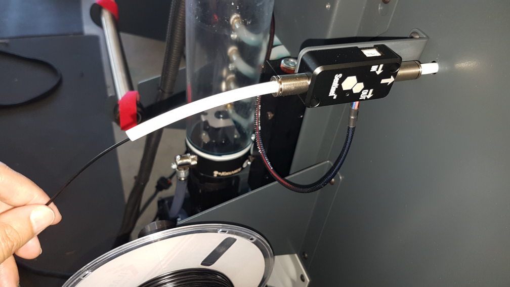
- Carefully feed the filament until it exits at the other end of the PTFE tube, found on the inside of the build chamber.
If the feed path upgrade kit is installed on the machine, some effort might be needed to feed the filament through the sensor found in the filament runout detector. If there is a restriction, carefully remove the filament out of the feed path and straighten the filament. Make sure the filament has a sharp 45 degree angle cut on the end.
Heat the Hot End(s)
When facing the front of the machine:
• Toolhead 0 (T0) is found on the left-hand side of the X-axis linear rail,
• Toolhead 1 (T1) is found on the right-hand side of the X-axis linear rail.
Use the Graphical User Interface (GUI), or web browser, to heat the toolhead(s) to the extrusion target temperature for the chosen material:
- Select Temp.
- For T0, enter the target temperature in the field under Target.
- Select the ON/OFF icon to power ON the T0 heater.
- Do steps 1 to 3 for the adjacent toolhead, if necessary.
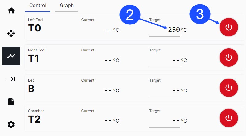
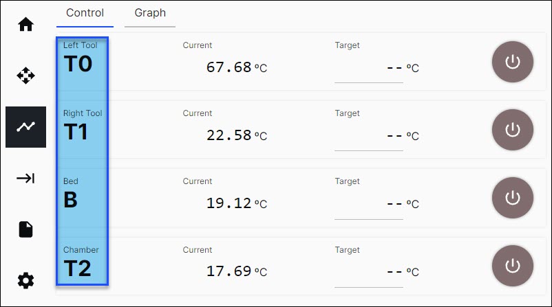
In Temp > Control, the machine components tags (labeled T0, T1, B, T2) are as follows:
• When the heater(s) are powered OFF, the tag(s) are BLACK in color.
• When the heater(s) are powered ON, and the temperature increases towards the target, the tag(s) are RED in color.
• When the heater(s) are at a stable target temperature, the tag(s) will return to BLACK in color.
Load Extruder and Purge
Do not touch the hot ends when the toolhead heater(s) are active. The temperatures in the hot end(s) range from 200°C to 500°C (390°F to 932°F) and will result in injury when touched.
To help load the filament into the extruder(s), use the GUI to move the X-axis gantry to the front of the machine along the Y-axis.
- Make sure the hot end is at the correct target temperature.
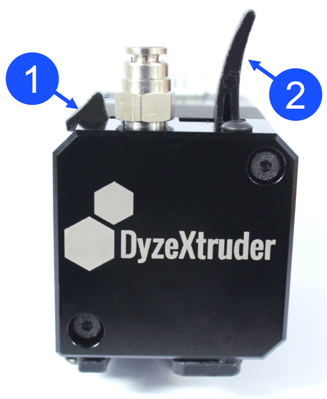
- Found on top of each extruder body is a tab (1) and a lever (2):
- Compress the tab (1) and lever (2) together with light finger pressure to temporarily lock the internal gears apart and let filament pass through.
- Compress the tab (1) and lever (2) together with light finger pressure to temporarily lock the internal gears apart and let filament pass through.
- Manually put the filament in the extruder, and carefully push it down into the hot end until it extrudes from the nozzle.
Do not push the filament too hard through the extruder assembly. This can cause a restriction in the feed path, and/or, cause damage to machine component(s).
• If there is a restriction when the filament is put into the extruder, remove and inspect the filament. Make sure the filament is straight and that there is a sharp 45 degree angle cut on the end. Do this step until the filament has been successfully installed into the extruder.
• If there is a restriction when filament is put in the extruder body, engage and disengage the extruder gears and carefully push the filament through the extruder. This will help line up the end of the filament between the drive gears.
• If the filament passed through the extruder, but will not feed into the PTFE guide tube, rotate the filament above the extruder to change the angle of approach when the filament is put into the PTFE guide tube. Make sure filament is straight and that the end is correctly cut at a 45 degree angle. - After filament has been successfully extruded from the nozzle, compress the extruder tab (1) and lever (2) to release the locking mechanism and engage the extruder drive gears onto the filament. When the extruder drive gears are engaged, the filament cannot be manually pulled from the extruder.
- Install the PTFE tube into the extruder fitting.
- On the GUI, select the Control > Motion.
- Select the Left Tool, set the Extrusion Distance (mm) to
100and set the Extrusion Speed (mm/sec) to5.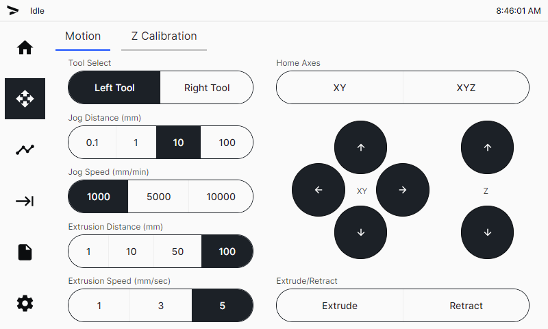
- Select
Extrudetwo times to feed 200 mm of the filament through the hot end. Filament will now be extruded from the nozzle. - Use the wire brush to clean the nozzle.
- Do steps 1 to 9 for the adjacent toolhead, if necessary.
Turn the power to hot end heater(s) OFF when there is no print in progress. Do not let the hot end heater(s) idle for an extended period of time without extrusion. This can cause the polymer filament to burn and make a blockage in the nozzle(s). Refer to Hot End Heater Timeout Feature (Klipper) or Hot End Heater Timeout Feature (Marlin).
Return to Service
- Make sure that you remove the tools from the dry box enclosure, if applicable.
- Close the lid to the LEFT and RIGHT dry box enclosures, if applicable.
- Make sure that you remove all the tools from the build chamber.
- Close the build chamber door.
- Home XYZ.