User Interface Overview
This page highlights the key features within SuperSlicer’s User Interface (UI).
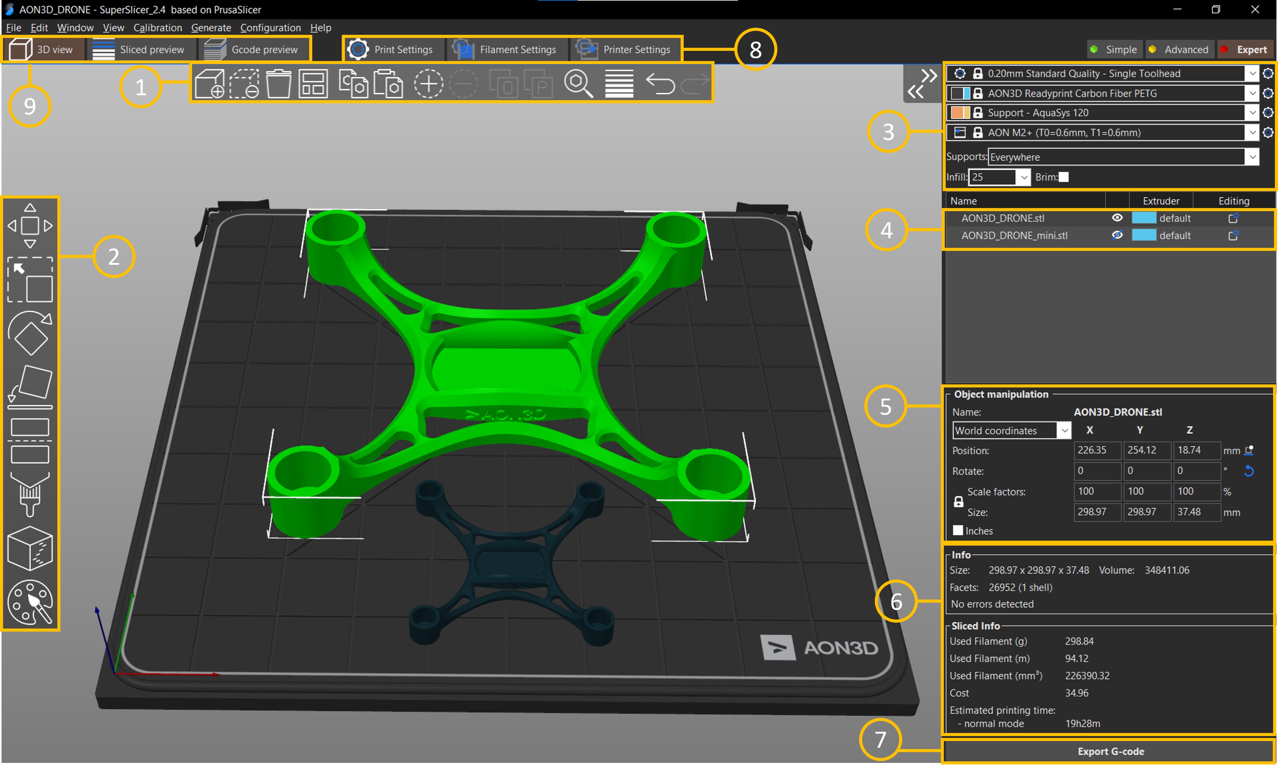
The main screen contains the build surface and model at the center of the UI.
1. Top Toolbar
The top toolbar is primarily used to add, remove, delete, arrange, copy and paste objects. Use the toolbar to create instances which are copies of objects that share the same properties. For example, any scaling factors, rotations, or sectioning operations to one part will reflect changes on the other part(s) that share the same instance. View and edit objects of the same instance in the Object Panel (4).
2. Left Toolbar
The left toolbar contains all the features necessary to Manipulate geometries and define Support and Seam placement.
- Move or
M- by default an object can be translated in X or Y when selected with the left-mouse button. Objects can be translated in a specific axis or lowered into the bed by selecting the move tool and dragging along the desired direction. Objects that are floating in SuperSlicer are automatically snapped onto the build surface. See lift objects from build surface for more details. - Scale or
S- similar to the move tool, objects can be scaled by clicking on the scale tool and dragging the respective dimension to enlarge or shrink the part. - Rotate or
R- objects can be rotated with respect to the three cartesian coordinates by selecting the rotate tool and dragging the arrow along the rotation axis. When parts are rotated into the bed, the slicer will take the lowest point of the geometry and place it on the build surface. Parts can be positioned into the bed by using the Move tool. - Place on face or
F- this tool highlights the major facets/surfaces detected on an object and places selected the face parallel to the build surface. - Cut or
C- separates the object in the Z-plane and allows user to keep or discard the split sections. To split an object in another plane, rotate the object first and then use the cut tool. - Paint-on Supports or
L- this is one of the most important tools in SuperSlicer to ensure that the imported models are supported adequately before a part is sliced. Select the desired object and select paint-on support to open the sub-menu.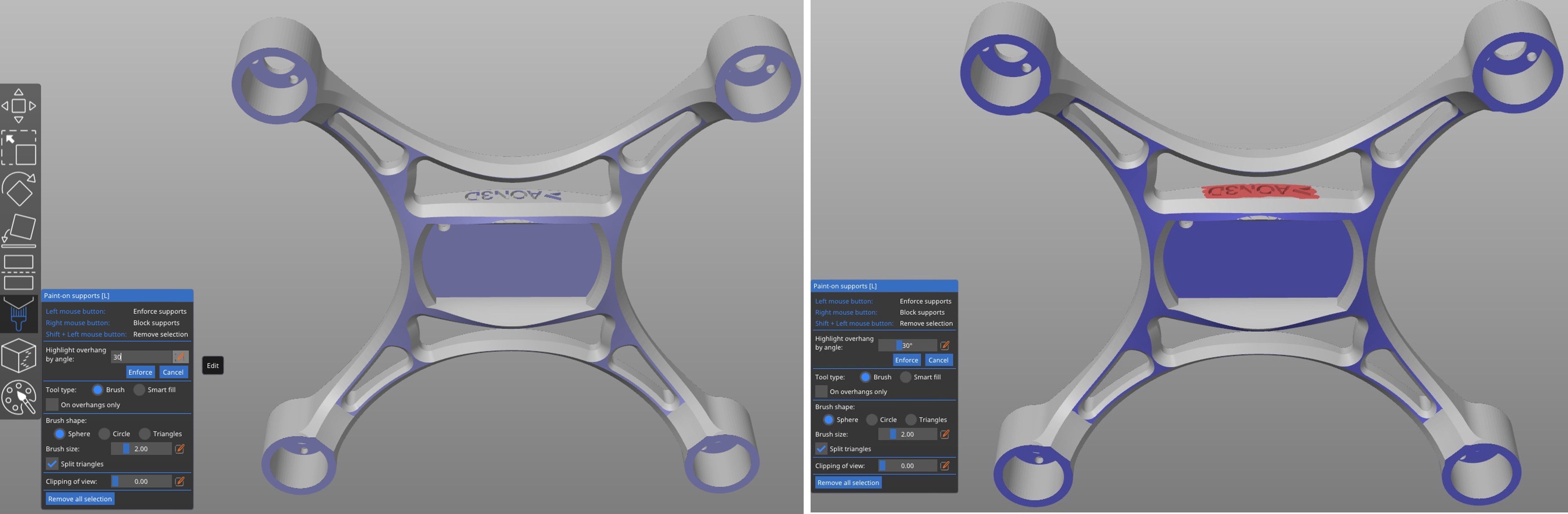 Highlight the regions where support is necessary by clicking the
 Editbutton and selecting the overhang angle relative to the vertical axis. The general rule of thumb is not to exceed 30° but this can vary between filaments. Once the desired angle is entered, click onEnforceto confirm the selected regions. Add support blockers to restrict support structures from being printed in specific areas by dragging the right mouse button over the region. In this example the text is highlighted in red to block support structures from being printed.
To select the regions to print supports manually, select theSmart fillandOn overhangs onlyoptions and click on the region with the left mouse button. - Seam painting or
P- An optional setting to improve the aesthetics of the part by allowing the user to control the location of the seam (start and stop points of each layer). This is useful for hiding seams in part corners or locating a seam around the boundaries of a feature for better-quality parts.
The multi-material painting feature is not currently supported on the AON M2+.
3. Process Control Panel
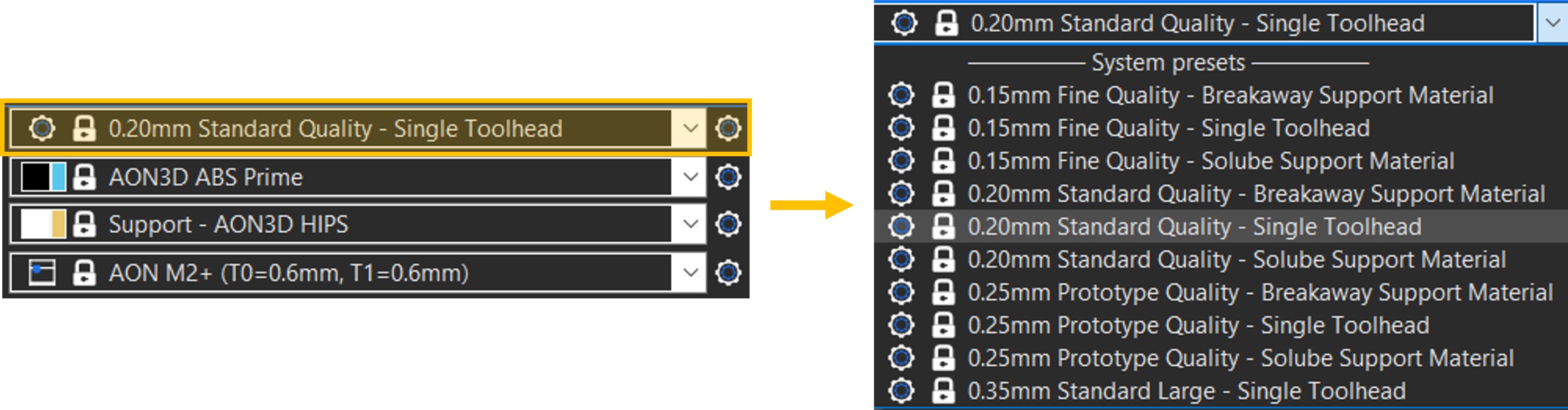
First option on the Process Control Panel is referred to as the Print Settings. In the drop-down menu there are multiple presets that enforce certain quality levels, in the general term of layer height. 0.15 mm delivering the finest quality, and 0.35 mm delivering rapid prototyping quality for large nozzles. Smaller layer heights result in finer quality parts, but also take longer to print.
Not all layer heights are compatible with all nozzle sizes. The general rule of thumb is to select a layer height that is 50% or less of the nozzle’s diameter. For example, the maximum layer height for a 0.4mm nozzle should be 0.2mm to ensure adequate layer bonding and part quality.
Note that the presets are labeled according to their respective layer height and type of support, if any. For each quality category there are Single Toolhead, Breakaway Support Material and Soluble Support Material options.
The user must select one of the Breakaway or Soluble Support Material Print Quality Selection options in order to print with both toolheads.
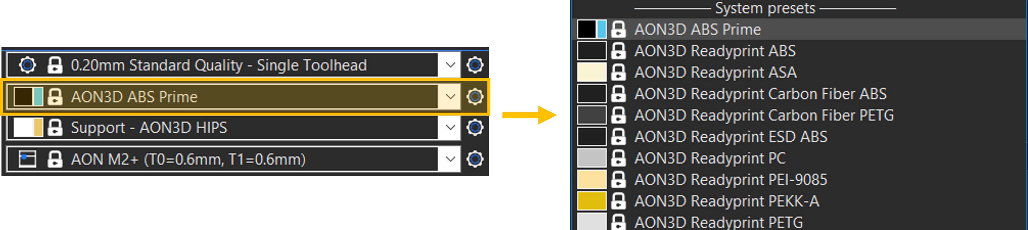
The second and third options on the Process Control Panel are referred to as the Filament Settings and correspond to toolheads T0 and T1 respectively. In the example above, AON3D Readyprint™ Carbon Fiber PETG is selected on T0 and Support - AquaSys®120 is selected on T1. The drop-down menu under each contains a list of filaments that have been validated with standard profiles including both model and support materials, by the AON3D Applications Engineering team.
If one of the Single Toolhead options under Print Quality Selection is selected, the T1 designated material will not apply/print. Select one of the Breakaway or Soluble Support Material Print Quality Selection options in order to print with both toolheads
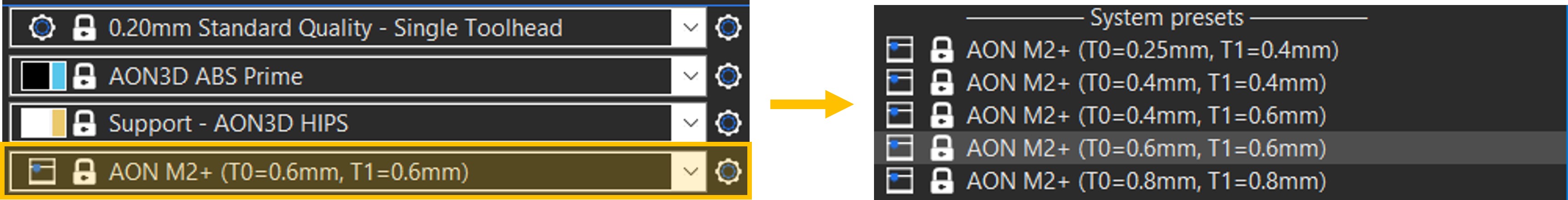
The final option on the Process Control Panel is the Printer Settings and is meant to reflect the toolheads configuration on the printer. For example, select the second option if the AON M2+ is loaded with a 0.6mm nozzle on T0 and a 0.6mm nozzle on T1.
These additional settings allows customization of how supports are applied to the geometry, the infill percentage of the part and if brims should be added to improve first-layer adhesion.
If everywhere is selected for supports, all regions of the geometry are supported that are above the threshold angle defined in the Support Material Settings within the Print Settings Tab. Change this to for support enforcers only to only apply supports in regions highlighted by the paint-on supports or choose none to restrict support generation.
Infill can be changed using the drop-down menu or in the Print Settings Tab under Infill.
4. Object Panel
The object panel displays all the objects uploaded in the file, the relationship between objects such as instances, and any geometry modifications applied such as paint-on supports. Hide objects by selecting the eye symbol.
5. Object Manipulation Panel
The object manipulation panel allows the user to position, rotate, scale, and size the selected object(s) numerically. To scale or size objects non-uniformly, select the lock symbol before entering the scale or size value.
6. Info Panel
The information panel contains the size of the bounding box around the object in mm as well as the volume in mm³. The number of facets that comprises the geometry is also indicated.
When an object is sliced using the Slice now button, this panel expands to include the Sliced Info. The used filament in grams (g), meters (m) and volume (mm³), cost in USD and estimated printing time information are displayed.
7. Export G-code
Once the geometry is sliced, the G-code can be created and exported using this button. The filename will include: date(YYYYMD)_GeometryName_T0-Size-Filament_T1-Size-Filament_PrintTime.
8. Print, Filament and Printer Settings Tabs
Process settings in SuperSlicer are broken down into Print, Filament and Printer settings. For more information on these settings, refer to the specific setting pages:
9. 3D view, Sliced preview and G-code preview Tabs
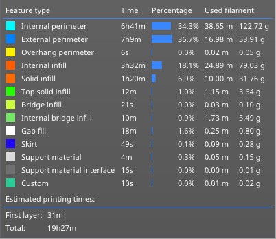
These tabs allow the user to toggle between 3 types of viewing options on the SuperSlicer UI. The 3D view is the default view which displays the geometry as imported. The Sliced Preview and G-code preview display the geometry as a sliced object. The G-code preview tab is more useful as it contains information on the feature types present in the geometry. Click on the individual features in the legend (shown below) to isolate the view to specific features.
Need help? Basic slicing support is available to all AON3D customers. For advanced support inquiries, an AON3D success plan may be required. Our Success plans help businesses get started fast, minimize downtime, and quickly become experts in industrial additive manufacturing.
Contact us at help@aon3d.com to get started or for Success Plan information.