Build Platform Adhesion
Achieving a successful first layer is the most important step of every print, forming the foundation of the part by anchoring it to the build platform. There are many factors controlling first layer performance. These factors must be controllable to balance first layer adhesion strength and ease of part removal.
Build Platform Compatibility
The printed material and build platform must not only provide mechanical adhesion via asperities, but they must also be chemically compatible. When using two different materials for dual tool prints, ensure that both materials are compatible with the build platform surface.
AON M2+ (CE), AON M2+ (R-NZ) and AON M2+ Machines
The following table indicates the adhesion behavior between validated filaments and compatible build platforms on the AON M2+ (CE), AON M2+ (R-NZ) and AON M2+ machines. The adhesion rating is listed for all build platforms along with the preferred build platform, which provides the best solution for the selected filament.
| Material | PC | PEI | CF-PEEK | Garolite G-10 |
|---|---|---|---|---|
| AON3D Readyprint™ ABS | Good | Preferred | Good | Good |
| AON3D Readyprint™ CF ABS | Good | Preferred | Good | Good |
| AON3D Readyprint™ ESD ABS | Good | Preferred | Good | Good |
| AON3D Readyprint™ ASA | Good | Preferred | Good | Limited |
| AON3D Readyprint™ HIPS | Good | Preferred | Good | Good |
| AON3D Readyprint™ PC | Not Recommended | Preferred | Limited | Limited |
| AON3D Readyprint™ PEI 9085 | Not Recommended | Good* | Preferred | Not Recommended |
| AON3D Readyprint™ PEKK-A | Not Recommended | Good* | Good | Preferred |
| AON3D Readyprint™ PETG | Good | Not Recommended | Good | Preferred |
| AON3D Readyprint™ CF PETG | Good | Not Recommended | Good | Preferred |
| AON3D Readyprint™ PPSU | Not Recommended | Preferred* | Limited | Not Recommended |
| AON3D Readyprint™ TPU-92A | Good | Good | Good | Preferred |
| AON3D ABS Prime | Good | Preferred | Good | Good |
| AON3D HIPS | Good | Preferred | Good | Good |
| Covestro Addigy® F1030 CF10 (CF PA) | Not Recommended | Limited* | Limited* | Preferred |
| Jabil PA 0600 | Good* | Good* | Not Recommended | Preferred |
| Jabil PA 4500 | Not Recommended | Untested | Not Recommended | Preferred |
| Jabil PA 4535 CF | Not Recommended | Good* | Good* | Preferred |
| Solvay KetaSpire® MS NT1 (PEEK) | Not Recommended | Limited | Good | Preferred |
| Solvay KetaSpire® CF10 LS1 (CF PEEK) | Not Recommended | Limited | Good | Preferred |
| SABIC LEXAN™ EXL AMHI240F (PC) | Not Recommended | Preferred | Limited | Not Recommended |
| Infinite Material Solutions AquaSys® 120 | Good | Good* | Good | Preferred |
| Infinite Material Solutions AquaSys® 180 | Not Recommended | Good | Preferred | Not Recommended |
| ThermaX™ MTS1 Support | Not Recommended | Preferred | Not Recommended | Not Recommended |
| ThermaX™ HTS2 High Temperature Support | Not Recommended | Preferred | Good | Not Recommended |
| TenneT PI | Not Recommended | Good** | Good** | Not Recommended |
| Victrex AM™ 200 FIL (LMPAEK) | Not Recommended | Not Recommended | Preferred | Good |
* The material prints on the build platform with the use of Nano Polymer Adhesive, an applied adhesion aid.
** The material requires the use of a raft printed in a compatible support material.
AON-M2 2020 and AON-M2 Machines
The following table indicates the adhesion behavior between validated filaments and compatible build platforms on the AON-M2 2020 and AON-M2 machines. The adhesion rating is listed for all build platforms along with the preferred build platform, which provides the best solution for the selected filament.
| Material | Aluminum Build Plate with Kapton® Surface | High-Temperature Build Plate |
|---|---|---|
| AON3D Readyprint™ ABS | Preferred* | Good |
| AON3D Readyprint™ CF ABS | Not Recommended | Not Recommended |
| AON3D Readyprint™ ESD ABS | Not Recommended | Not Recommended |
| AON3D Readyprint™ ASA | Preferred* | Not Recommended |
| AON3D Readyprint™ HIPS | Preferred* | Good |
| AON3D Readyprint™ PC | Not Recommended | Preferred |
| AON3D Readyprint™ PEI 9085 | Not Recommended | Preferred |
| AON3D Readyprint™ PEKK-A | Not Recommended | Preferred |
| AON3D Readyprint™ PETG | Not Recommended | Not Recommended |
| AON3D Readyprint™ CF PETG | Not Recommended | Not Recommended |
| AON3D Readyprint™ PPSU | Not Recommended | Preferred |
| AON3D Readyprint™ TPU-92A | Not Recommended | Not Recommended |
| AON3D ABS Prime | Preferred* | Good |
| AON3D HIPS | Preferred* | Good |
| Covestro Addigy® F1030 CF10 (CF PA) | Not Recommended | Preferred |
| Jabil PA 0600 | Preferred* | Limited |
| Jabil PA 4500 | Not Recommended | Not Recommended |
| Jabil PA 4535 CF | Not Recommended | Not Recommended |
| Solvay KetaSpire® MS NT1 (PEEK) | Not Recommended | Preferred |
| Solvay KetaSpire® CF10 LS1 (CF PEEK) | Not Recommended | Preferred |
| SABIC LEXAN™ EXL AMHI240F (PC) | Not Recommended | Preferred |
| Infinite Material Solutions AquaSys® 120 | Not Recommended | Preferred |
| Infinite Material Solutions AquaSys® 180 | Not Recommended | Not Recommended |
| ThermaX™ MTS1 Support | Not Recommended | Preferred |
| ThermaX™ HTS2 High Temperature Support | Not Recommended | Preferred |
| TenneT PI | Not Recommended | Not Recommended |
| Victrex AM™ 200 FIL (LMPAEK) | Not Recommended | Not Recommended |
* The material prints on the build platform with the use of Nano Polymer Adhesive, an applied adhesion aid.
First Layer Adhesion Control
Mechanical adhesion is achieved by allowing material to reach a viscosity that allows the material to flow into the asperities and interlock with the build platform. The interfusion between the first layer and build platform is a major source of adhesion. Increasing the surface roughness of the build platform and/or decreasing the polymers viscosity increases first layer adhesion by allowing more material into the asperities.
Chemical adhesion controls the surface energy and miscibility behavior of the first layer. Miscibility between the extruded material and the build platform can be selected, allowing for controllable adhesion. Greater flexibility on the thermal process window may be achieved by selecting miscibility parameters of the material selection.
Mechanical and chemical adhesions are both time and temperature dependent variables - process parameter optimization impacts the first layer success. However, the adhesion force may be so great that part and/or build platform damage may occur.
The cleanliness of the build platform surface is another factor. The surface must be free or contaminants such as dust, grease, old adhesives, and other material remains. We recommend cleaning the bed surface or use fresh surface before each print.
Do not clean the build platform while hot. Only perform any cleaning on a cool build platform, to reduce the risk of burn or electric shock.
Adhesion Aid
Depending on the compatibility of the model, support, and build platform material, adhesion aids may be needed to increase first layer performance. Alternatively, if adhesion is too great where damage occurs to the part and/or build platform during part removal, an adhesion aid can be used as a release agent by decreasing adhesion between the two interfaces.
Nano Polymer Adhesive (NPA) is an adhesion aid product suited for both low and high-temperature materials on the AON3D machines. We recommend two alternating light layers of NPA on the build platform if needed to increase or decrease first layer adhesion.
Z Offset
The Z offset controls the nozzle spacing in relation to the build platform. Appropriate spacing ensures that the first printed layer adheres to the build platform. By controlling the nozzle-to-bed distance, the effective contact area of the print to the build platform can be adjusted. Consequently, having an appropriate distance prevents material accumulation at the nozzle, reducing potential toolhead collisions.
Decreasing the nozzle-to-bed distance increases first layer adhesion and vice-versa. Micro-stepping adjustments may be needed while printing the first layer to ensure an appropriate distance and correcting for uncertainties in nozzle spacing.
The following set of images shows prints with Z offsets that are too small (bed too close), too big (bed too far), and just right.
A print with the Z offset being too small, ie. the bed is too close to the nozzle.
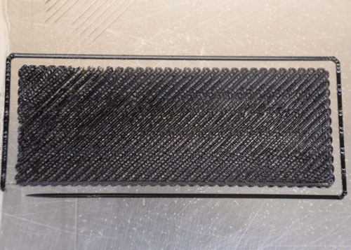
The extruded bead becomes overly constrained by neighboring extrusions. The deposited material is being ejected beyond the toolhead path of the nozzle tip. Three failure types may occur:
-
Immediate layer failure occur with an accumulation of material around the nozzle tip. Spacing is too close, causing the dislodgement of neighboring extrusions as new extrusions are being placed.
-
Protrusion of material creates a collision risk with the toolhead. Collision between the toolhead and part may result in layer shifting with part and/or toolhead damage.
-
Very close spacing may cause increased heat exposure of the first layer and build platform. The first layer of the part and build platform may be welded, making part removal impossible.
A print with the Z offset being too big, ie. the bed is too far from the nozzle.
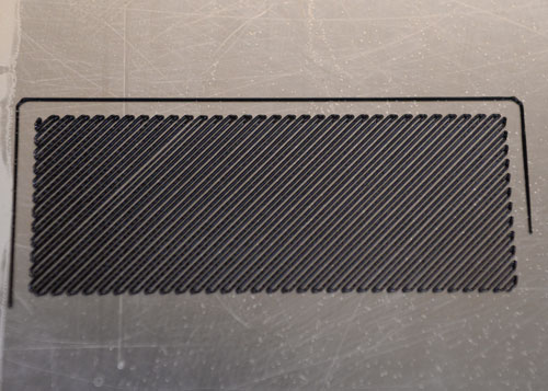
Not enough material is in contact with the build platform. The amount of extruded material deposited into the asperities of the build platform is reduced if the nozzle-to-bed distance is too big. The lack of surface area and interlocking of bodies reduce the first layer adhesion.
A print with a perfectly adjusted Z offset
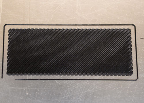
Optimal bonding with the neighboring extrusions as each pass is deposited while they are deformed into rectangular/elliptical sections.
First Layer Settings
Full process parameter development must include first layer adhesion control. Temperature, first layer settings, and additions influence adhesion. Internal stresses that accumulate during processing can be controlled through the environmental temperature.
Extrusion and Bed Temperature
Higher extrusion temperature within recommended precessing range may result in greater adhesion force to the build platform. Alternatively, lower extrusion temperatures may decrease adhesion which may be needed if part and/or build platform damage occurs during part removal. The closer the build platform is to the model material’s glass transition temperature (Tg), the greater the adhesion force to the bed with minimal accumulation of stress due to polymer shrinkage. If the bed is above Tg, the bottom of the part may become too soft to stay in place and lose its shape. Temperature set points can be specified per layer such as higher extrusion temperatures for the initial layers that gradually decrease in the part.
For amorphous printing:
- The first few layers of the part can be extruded at a higher/lower extrusion temperature for an increase in first layer performance.
- Extrusion temperature can be adjusted to optimal processing temperatures over many layers to avoid severe temperature gradients that may impose large internal stresses.
For semi-crystalline printing:
- Extrusion temperature can be controlled to adjust first layer adhesion.
- Extremely high extrusion temperatures cause large degrees of crystallization.
- Material shrinkage from crystallization may cause the part to warp and detach from the build platform: additional parameters must be considered to improve first layer performance.
Extrusion Height and Width
A thick first layer provides a stable base, making it less sensitive to irregularities in the build platform flatness.
Values of 100-150% of the overall layer width and height are sufficient to provide a stable base.
Values under 100% for layer height help decreasing the adhesion if part removal causes part and/or build platform damage.
Printing Speed
Slower first layer printing speeds allow the extrusions to mechanically and chemically bond with the build platform. Amorphous extrusions may accumulate less stress when extruded at a slower printing speed, decreasing the amount of polymer shrinkage. Whereas high degrees of crystallization may occur with semi-crystalline extrusion due to the accumulation of heat from slower printing speeds. Avoid very slow printing speeds at high extrusion temperatures as the material in the nozzle may degrade and clog.
Raft Addition
A raft is a sacrificial base printed below the part used to increase or decrease first layer adhesion. The first raft base layers are thick but sparsely filled and the top raft layers are thin to create a smooth surface for the part to print on. A raft can be controlled by the infill percentages of top layers, separation distance between part and raft, print speed of first model layer onto the raft, and temperature of the raft and the first layer of the part.
A raft can be printed in the same material as the model, or in a different material. Geometries with small first layer surface areas can be increased by using a raft as a stable base. If the model material has poor compatibility with the build platform material, a raft made out of a material that provides improved adhesion to both the bed and the model material can be used.
For additional first layer adhesion, the first few layers of the raft can be printed at a higher extrusion temperature, then gradually decreased in the raft to optimal processing temperatures. If the model material has too great of a first layer adhesion, which results in part and/or build platform damage during part removal, a raft can be used to decrease first layer adhesion.
Brim Addition
A brim outline is a single track of material deposited around the outside perimeter of a part used to increase first layer adhesion. The outlines together are referred to as a brim. Brim outlines increase the surface area of the first layer on the build platform, increasing the adhesion force to the bed.
The number of brim outlines can be controlled depending on the severity of insufficient adhesion to the bed. Values of 5 up to 20 brim outlines are commonly used.
The number of brim layers can also be controlled, 1 is sufficient for most situations. More than 1 layer of brim can be used if the brim separates from the model. The brim may separate from the model if the Z offset for the first layer is not appropriate and/or polymer shrinkage force is much greater than the force between the brim outline and model.
Anchors
Most commonly used for high-temperature amorphous and semi-crystalline polymers, anchors minimize material shrinkage.
- Anchors, similar to brim outlines, are used to increase first layer area.
- Anchors are added to the model using an external CAD software and attached on specific warp prone areas of the geometry.
- The size and shape of the anchors may be modified based on the part such as pyramids or circular tabs.
- Anchors can be of single layer or can scale the entire model.
Chamber Temperature
Thermal stability is a major contributor to first layer performance and overall print success. Refer to the Part Warping section for information about optimal chamber temperature for amorphous and semi-crystalline printing. Follow the recommended printer pre-heat times to minimize undesirable thermal stability effects on prints.
Part Warping
Part warping is one of the most frequently experienced issues. The first layer must anchor the part to the build platform. The adhesion strength must be large enough to resist the accumulation of internal stresses during the printing process. Stress is concentrated at corners and parallel to long, thin shapes. Warping due to material shrinkage is unavoidable but can be managed. The amorphous or semi-crystalline nature of the processed material may influence the degree polymer shrinkage while printing.
Processing Amorphous Polymers
Warping of amorphous polymers is mostly due to the accumulation of stress developed during the deposition of layers. As extrusions cool down to equilibrate with the chamber temperature, polymer shrinkage may occur and induce stress in the part. The temperature change causes the polymer to transition from a fluid at a high temperature, to a solid at a temperature below its glass transition temperature (Tg). To reduce the temperature gradient, the extrusion temperature can be decreased within its acceptable processing range and the chamber temperature can be increased. For most amorphous materials, we recommend printing in a chamber temperature below but close to the Tg to minimize part warping and/or deformation.
Amorphous polymers with a low Tg may perform well with minimal warping due to a decreased temperature gradient. Part warping may be difficult to manage for polymers with Tg temperatures greater than the maximum operating chamber temperature. Larger temperature gradients may cause greater shrinkage rates. Thus, amorphous polymers will shrink proportionally to its Coefficient of Linear Thermal Expansion and the temperature difference.
Processing Semi-Crystalline Polymers
Printing semi-crystalline materials is considered advanced printing for expert users.
Part warping can be minimized by processing semi-crystalline polymers in a amorphous fashion. Processing semi-crystalline polymers in a semi-crystalline fashion causes the molten material to crystalize after deposition. Material shrinkage may be induced as the polymer crystallizes due to the orderly arrangement of chains. Different material crystallization rates and processing conditions can affect the severity of warping. Avoid very high extrusion temperatures as they may increase crystallization rates. For most semi-crystalline materials, set the chamber temperature below but close to the Tg.
Additional variables such as toolhead paths can influence the degree of crystallization. Isometric crystallization of a part is generally favorable for even shrinkage. Uneven shrinkage may cause extreme part warping and/or deformation. If the toolhead path goes over a localized region on the same layer multiple times, the accumulation of heat may cause an increase of crystallized material specifically in that location. Process parameters such as Internal Infill Pattern and/or Single Extrusions can be adjusted to minimize the amount of time the toolhead dwells over the same region.
Part Removal
Wear protective eyewear and gloves during part removal. Printed parts can suddenly fracture, potentially causing injury to yourself from sharp structures.
Avoid removing the part from the build platform while the machine is still hot. Part shrinkage, deformation, and warpage due to thermal shock may occur from removing the part before letting the machine cool. Remove the part from the build platform once the machine has cooled down to room temperature for best results.
Easy of part removal from the build platform depends on first layer adhesion: strong first layer adhesion makes part removal more difficult. The difference in coefficients of thermal expansion between the part and build platform materials may facilitate part removal. For example, a part made out of a specific material may shrink a greater amount than the build platform at room temperature. If the involved forces during material shrinkage is great enough, the first layer adhesion may be compromised - facilitating in part removal.
Some materials may be peeled off the build platform by hand at room temperature. Whereas other materials will require the use of a spatula and mallet to shear the part off the build platform due to very high first layer adhesion forces. Be cautious as the part first layer adhesion to the build platform may be greater than the strength between each layer. The first few layers of the part may stick to the build platform, detaching from the rest of the model.