Quick Start (Klipper)
The following guide provides a high-level order of operations to ensure ongoing success with the AON M2+ (CE), AON M2+ (R-NZ) and AON M2+ machines that operates with the Klipper-based firmware. Make sure that all linked articles are read in their entirety as this section is only meant to serve as a quick start overview.
The instructions that follow are for the AON M2+ (CE), AON M2+ (R-NZ) and AON M2+ machines that have the Klipper-based firmware only.
Refer to Quick Start (Marlin) for AON M2+ (CE), AON M2+ (R-NZ) and AON M2+ machines that have the Marlin-based firmware.
- 1. Basic System Setup and Preparation
- 2. Calibration
- 3. Run the G-Code
1. Basic System Setup and Preparation
1.1. Load G-Code File Through Web Browser
To upload a file into the GUI:
- On the web browser, select Files.
- Select
+andUploadto import the G-code file onto the AON3D machine.
1.2. Clean the Machine
- Make sure that the machine is clean and that there is no unwanted material(s) around the lead screws and/or around the linear guides and guide rails.
- Make sure that the nozzle is clean. Use the wire brush to clean the nozzle while it is set above the material’s glass transition temperature (Tg).
- Make sure that the print surface is clean and free of solvents and/or unwanted materials.
Refer to Clean Build Platform and Build Chamber.
Do not use compressed air to clean the machine component(s) unless otherwise specified. The use of compressed air can cause damages to machine component(s).
1.3. Load/Replace Filament
Make sure there is sufficient filament on the spool before a print is started. Simplify3D® and SuperSlicer give an estimate on the weight of filament necessary for each part in the G-Code viewer. To calculate the weight of filament necessary:
- Weigh the spool of filament to be used.
- Subtract the weight of an empty spool from the weight of the spool of filament to be used.
- Compare the above results to the estimated weight in Simplify3D®.
- Refer to the Load Filament procedure.
- Refer to the Replace Filament procedure.
1.4. Prepare Heater Block Assembly
Install the heater block assembly that has a nozzle size that matches your print profile. Refer to Replace Heater Block Assemblies.
1.5. Prepare the Build Platform
1.5.1. Select the Build Platform
Refer to the Build Platform Adhesion guide to determine a compatible build platform.
1.5.2. Apply Adhesion Aid
Some filament and build platform combinations require the use of an adhesion aid.
- The Nano Polymer Adhesive can be applied to increase build platform adhesion.
- The Nano Polymer Adhesive can be used as a release agent to facilitate part removal without damaging the part and/or PEI build sheet.
1.5.3. Install Build Platform Start Vacuum Bed Feature
The build platform must be correctly installed to get satisfactory print results.
Refer to the Install Build Sheet procedure.
1.6. Preheat Machine Components
1.6.1. Preheat Build Chamber and Bed
- Select Files
- Select the filename to print.
- Select
Preheat
1.6.2. Wait for Thermal Equilibrium (Heat Soak)
Refer to Preheat Build Chamber Components.
2. Calibration
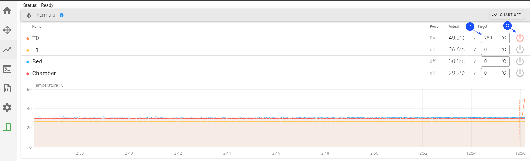
2.1. Heat the Heater Block Assembly to Bed Temperature + 50°C
Use the Graphical User Interface (GUI) to heat the toolhead(s) to the bed target temperature + 50°C:
- Select Temperatures.
- For T0, enter the bed temperature in the field under Target.
- Select the ON/OFF icon to power ON the
T0heater. - Do steps 1 to 3 for the adjacent toolhead, if necessary.
Turn the power to hot end heater(s) OFF when there is no print in progress. Do not let the hot end heater(s) idle for an extended period of time without extrusion. This can cause the polymer filament to burn and clog the nozzle(s). Refer to Hot End Heater Timeout Feature.
2.2. Calibrate the Z-Axis
AON3D recommends calibrating the Z-axis before every print.
Refer to the Z Offset Calibration (M2+ Klipper) procedure. Repeat for the adjacent toolhead, if required.
2.3. Calibrate X/Y Toolhead Offsets
If a print uses the two toolheads for the same print, the toolheads must be calibrated along the X/Y-axes before a print is started. The X/Y-axes calibration procedure adjusts the coordinate system of the two toolheads to be in line with each other.
2.3.1. Print X/Y Calibration - 0.1 mm Scale
To make sure that the X/Y Toolhead Offsets Calibration procedure is done correctly, AON3D provides STL files.
Refer to the X/Y Toolhead Offsets Calibration procedure.
2.3.2. Enter Correction Factor
When the print is complete:
- Open the build chamber door.
- Use the parts removal tool to remove the printed scale from the build print surface.
- Close the build chamber door so as to not let the build chamber temperature decrease.
- Examine the lines to calculate the necessary T1 offset(s) to align the two toolheads.
- Select Control > XY Calibration.
- Select
0.1as the Offset Adjustment Distance (mm). - Use the
-or+button to input the offset value on the X-axis. - Use the
-or+button to input the offset value on the Y-axis. - Select
SAVEto save the offsets.
2.3.3. Re-Print 2 to 3 Times
Repeat the X/Y calibration - 0.1 scale print and adjust the X/Y Toolhead Offsets until the X-axis and Y-axis scales center lines are aligned.
3. Run the G-Code
3.1. Start the Print
- On the GUI/web browser, select Files.
- Select the filename to print.
- Select
Printon the file to print. - Select
Printto confirm.
3.2. Evaluate the First Layer and Live Adjust Z-Axis Offset
- Make sure that the quality of the first layer height is correct before a print can continue.
- The Z offset calibration can be adjusted in minute increments to help get the correct first layer:
- Select Control > Z Calibration tab.
- Select Tool Adjustment Distance, and select
0.2,0.1or0.05increment. - Under Adjust Printing, select
FartherorCloserto adjust the distance between the build platform and the nozzle.- Select
Fartherto move the build platform down (away from the nozzle). - Select
Closerto move the build platform up (toward the nozzle).
- Select