X/Y Toolhead Offsets Calibration
| Model | [•] AON M2+ (CE) | [•] AON M2+ (R-NZ) | [•] AON M2+ | [•] AON-M2 2020 | [•] AON-M2 |
| Category | [ ] Preventive | [ ] Corrective | [•] Calibration |
Summary
The procedure that follows gives instructions on how to calibrate the T0 and T1 relative positions along the X/Y-axes. Well-calibrated X/Y toolhead offsets can prevent shifts and other print defects caused by misalignment.
Estimated time: 30-45 minutes
Tools
| Qty | Description | Specification |
|---|---|---|
| N/A | N/A | N/A |
Parts Information
None required.
Personal Protective Equipment
| Qty | Description | Minimum Specification |
|---|---|---|
| 1 | Safety Eyewear | ANSI/ISEA Z87.1 |
| 1 | Heat-resistant Gloves | EN 407-2004 |
Procedural Index
- When to Calibrate the X/Y Toolhead Offsets
- X/Y Toolhead Offsets Calibration Files
- X/Y Calibration Procedure
When to Calibrate the X/Y Toolhead Offsets
The X/Y toolhead offsets calibration procedure must be performed for prints that use both toolheads on the same print model.
It is common practice to calibrate the X/Y toolhead offsets as part of the setup process to make sure that both toolheads are correctly aligned with each other along the X/Y-axes.
AON3D recommends that the X/Y toolhead offsets be calibrated when:
- The machine is moved and/or leveled.
- There is a change of ±20°C (±68°F) in component temperature(s).
- Heater block assembly adjustments, removal, maintenance and/or repairs occur.
Make sure to use the same filament material, heater block assemblies (nozzle orifice diameter), and target temperatures for calibration as selected to print your part(s).
X/Y Toolhead Offsets Calibration Files
AON3D provides X/Y offset scale calibration files to help with the X/Y toolhead offsets calibration process. The .zip file must be imported/extracted to a computer and correctly oriented onto the Simplify3D® build plate. For best results, make sure to use the same print parameters on the scale files as in your actual print when a .gcode file is made.
Two X/Y offset scales are included in the .zip file:
- 0.1 mm offset scale - 0.4 mm nozzle (for 0.25 mm to 0.4 mm nozzles)
- 0.1 mm offset scale - 0.6 mm nozzle (for 0.6 mm to 1.2 mm nozzles)
How to Use the X/Y Toolhead Offsets Calibration Files
- The X/Y calibration files are used like a vernier caliper.
- When you use the provided calibration scale, each division represents a 0.1 mm offset.
- To read the scale, identify the two divisions that best line up with each other.
- To calculate the offset, count the lines from the point of origin (center) to the mark that lines up with the fixed scale and multiply by 0.1 mm.
- Lines to the left of the point of origin are negative offsets. Lines to the right are positive offsets.
- All X/Y offset adjustments are made to T1.
The printed calibration scale has the results shown below. With the 0.1 mm vernier constant, the user would calculate the offset adjustments as follows:
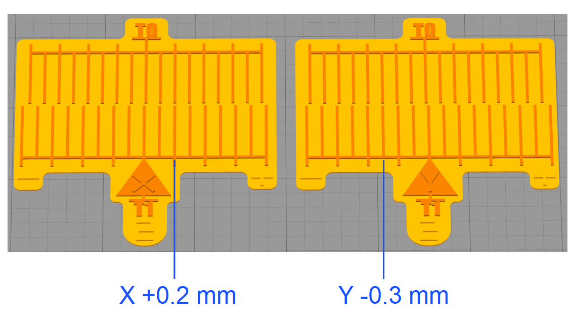
X-Axis Scale:
- The T0 and T1 printed lines are aligned in the positive vernier constant (alignment occurs to the right from the point of origin), which results to a positive value of 0.1 mm.
- There are a number of two lines indicated on the printed scale from the point of origin, which give us a value of 2.
- The formula is as follows: (0.1 x 2) = 0.2 X-axis offset on T1.
Y-Axis Scale:
- The T0 and T1 printed lines are aligned in the negative vernier constant (alignment occurs to the left from the point of origin), which gives us a negative value of -0.3 mm.
- There are a number of three lines indicated on the printed scale from the point of origin, which give us a value of 3.
- The formula is as follows: (-0.1 x 3) = -0.3 Y-axis offset on T1.
X/Y Calibration Procedure
Print Preparation
Load filament
Load filament into both toolheads. Refer to Load Filament.
Preheat Build Chamber Components
Make sure that there are no prints on the build surface. Remove print(s) before the procedure that follows is started. Failure to do so can cause a collision and can cause damage to the machine component(s).
Before the calibration procedure is started, it is necessary to let all build chamber components get to a stable print temperature.
Preheat Build Chamber Components to the target temperatures for the materials selected before a print is started.
Calibrate Z Offset
Calibrate the Z offsets on T0 and T1.
- For the AON M2+ (CE), AON M2+ (R-NZ), and AON M2+ machines that have the Klipper-based firmware, refer to the Z Offset Calibration (M2+ Klipper) procedure.
- For the AON M2+ (CE), AON M2+ (R-NZ), and AON M2+ machines that have the Marlin-based firmware, refer to the Z Offset Calibration (M2+ Marlin) procedure.
- For the AON-M2 2020 and AON-M2 machines, refer to the Z Offset Calibration procedure.
Calibration File Preparation
The procedure that follows uses the 0.1 mm X/Y offset scale for the 0.6 mm nozzle, with ABS loaded in both toolheads, to describe the X/Y toolhead offsets calibration procedure. If you are using different materials, nozzle orifice diameter(s), the steps that follow are similar, but you will need to adjust the process settings accordingly.
AON3D recommends the use of two spools of ABS filament of different colors the first time the X/Y toolhead offsets are calibrated, and/or when the user wants to practice this procedure. Filaments of different colors make a contrast that helps distinguish the prints on T1 from the prints on the T0.
- Download the XY calibration files and unzip. Different files for calibration are provided:
- One set for a 0.4 mm nozzle with a vernier constant of 0.1 mm.
- Factory file for Simplify3D® V4
- Factory file for Simplify3D® V5
- G-code prepared for ABS
- STL files
- One set for a 0.6 mm nozzle with a vernier constant of 0.1 mm.
- Factory file for Simplify3D® V4
- Factory file for Simplify3D® V5
- G-code prepared for ABS
- STL files
- One set for a 0.4 mm nozzle with a vernier constant of 0.1 mm.
- Open the .factory file with Simplify3D® that corresponds with the correct nozzle orifice diameter.
- If the calibration procedure is for ABS, use the .g-code file and refer directly to X/Y Toolhead Offsets Calibration Procedure.
- If the calibration procedure is for other materials than ABS and HIPS, edit both print processes.
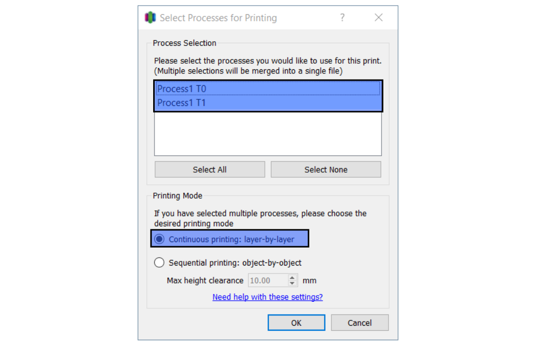
- Select Prepare to Print!, select both processes, and select Continuous Printing: layer-by-layer.
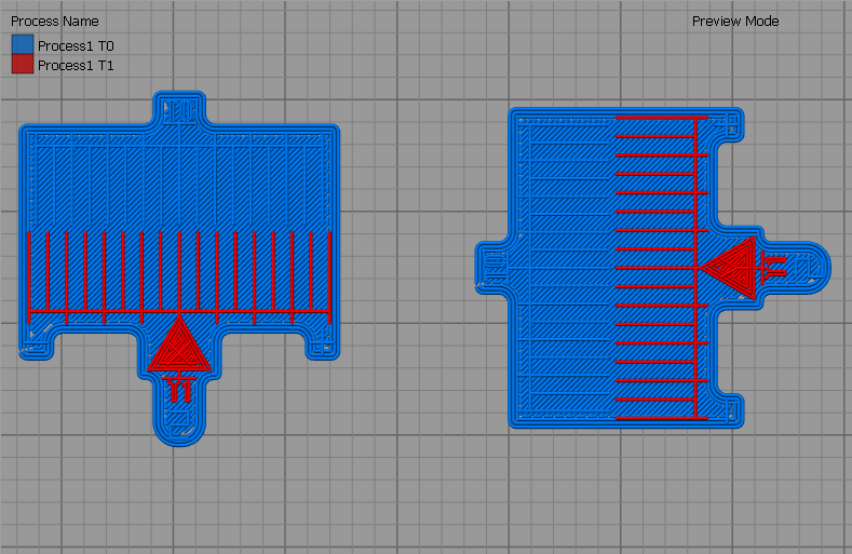
- Preview the process. Make sure that the T1 process is only used for the T1 scale.
- Select Save to generate the .gcode file.
The choice of material(s) used can have an effect on the factors that follow, and may need to be adjusted in the Simplify3D® process settings:
• Print speed(s)
• Brim and/or raft options
• Thin wall option(s)
• Temperature(s).
X/Y Toolhead Offsets Calibration Procedure
- All units of measurement are metric (mm).
- Machine default offset values are 0 mm for the X/Y axes.
- Offset calibration values must not be more than 5 mm. An offset of ±2 mm in the X/Y axes is typical.
The X/Y offsets can be entered on the GUI/web browser with the use of the Control > XY Calibration.
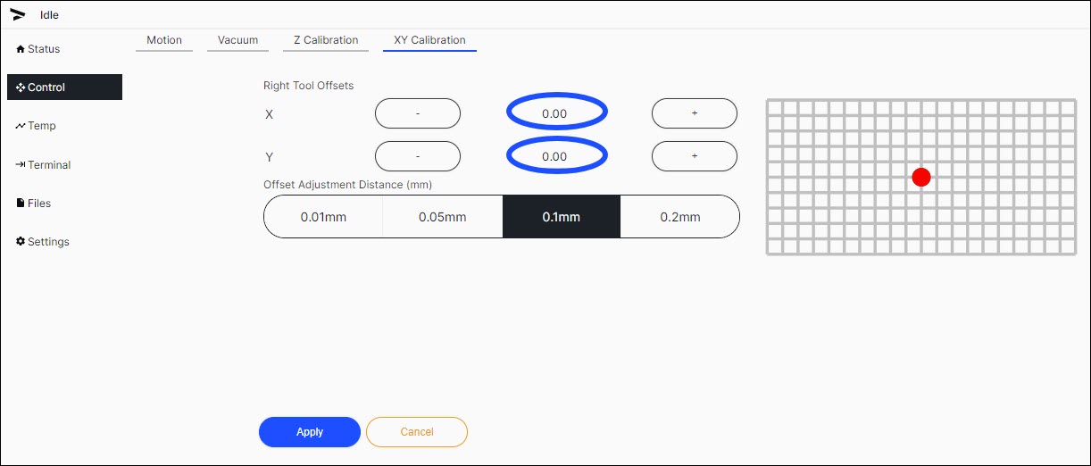
The X:0.00, Y:0.00 offsets are the default values, and have not been adjusted. Note that the T1 (red dot) overlaps the T0 (black dot).
- Upload the .gcode file into the GUI:
- On the web browser, select Files.
- Select
Upload Files, and import the .gcode file onto the AON3D machine.
- Enter the target temperatures for both toolheads.
- Select Temperatures for the Klipper-based firmware
- Select Temp for the Marlin-based firmware
- Let both toolheads get to the target temperatures.
- On the GUI/web browser, select Files.
- Select
Printon the calibration file to print. - Select
Printto confirm.All machine components are hot at this point. Wear the correct personal protective equipment to prevent injuries.
- Select
- When the print is complete, open the build chamber door, and use the parts removal tool to remove the printed scale from the build print surface. Make sure to close the build chamber door as to not let the build chamber temperature decrease.
- Examine the results. If the T0 and T1 center marks are not aligned with each other, add the printed offset values to the existing T1 offset values.
- Repeat the X/Y calibration - 0.1mm scale print and adjust the X/Y Toolhead Offsets until the X-axis and Y-axis scales center lines are aligned.
This is an iterative process, two or more attempts are necessary to obtain proper alignment. New offset values need to be added from the current offset values.
Examples
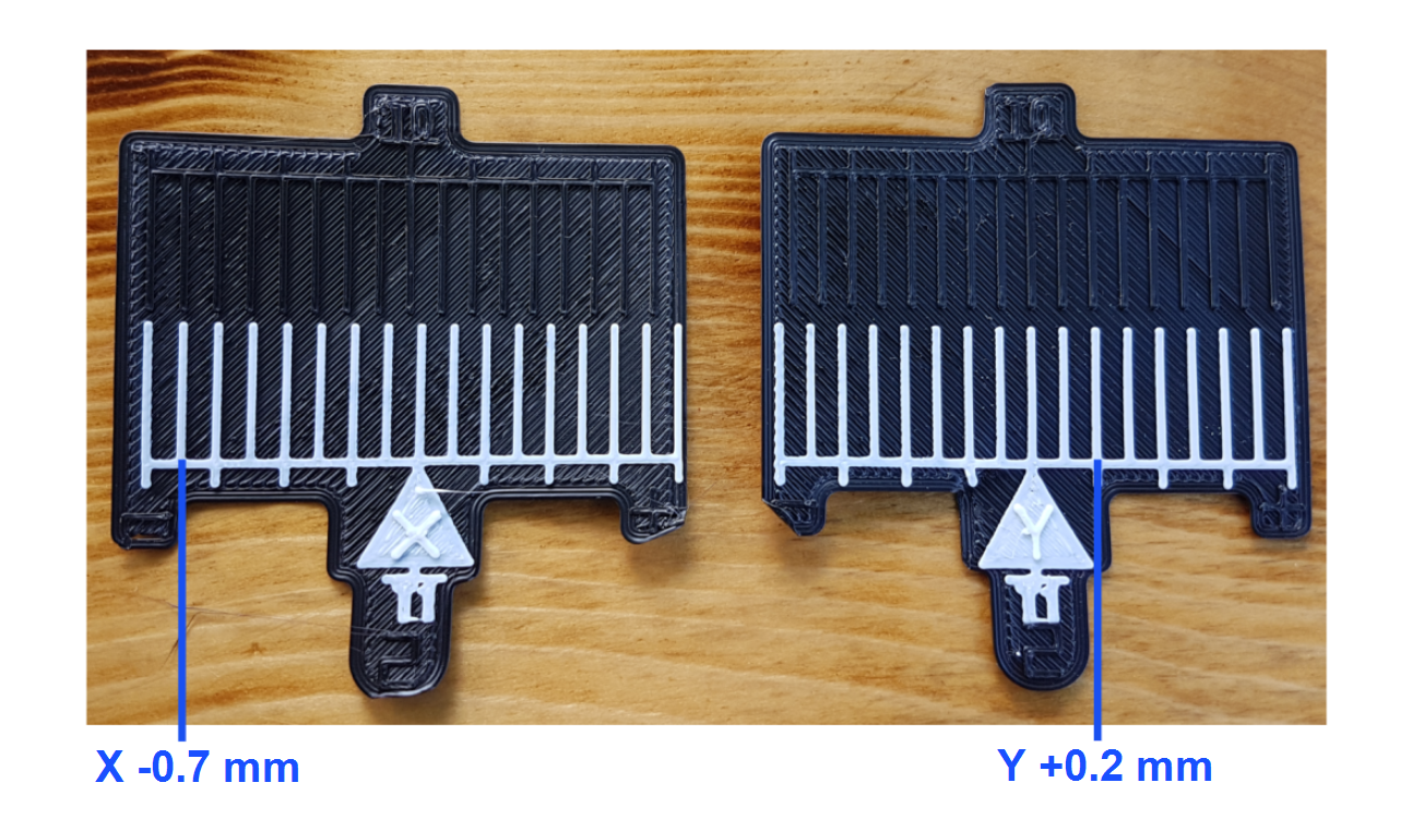
First X/Y Calibration Attempt
- The first printed scale gives the information that follows:
- X-axis: The T0 and T1 align at seven lines to the left (negative value) from the point of origin (T0).
- The formula is as follows: -0.1 x 7 = -0.7 offset is necessary on the T1 X-axis.
- Y-axis: The T0 and T1 align at two lines to the right (positive value) from the point of origin (T0).
- The formula is as follows: 0.1 x 2 = 0.2 offset is necessary on the T1 Y-axis.
- The formula is as follows: 0.1 x 2 = 0.2 offset is necessary on the T1 Y-axis.
- X-axis: The T0 and T1 align at seven lines to the left (negative value) from the point of origin (T0).
- Select Control > XY Calibration.
- Select
0.1mmas theOffset Adjustment Distance (mm). - Use the
-button to input-0.7on the X-axis. - Use the
+button to input0.2on the Y-axis. - Save the offsets:
- Select
SAVEto save the offsets on the Klipper-based firmware. - Select
Applyto save the offsets on the Marlin-based firmware.
- Select
- Print the same calibration .gcode file a second time.
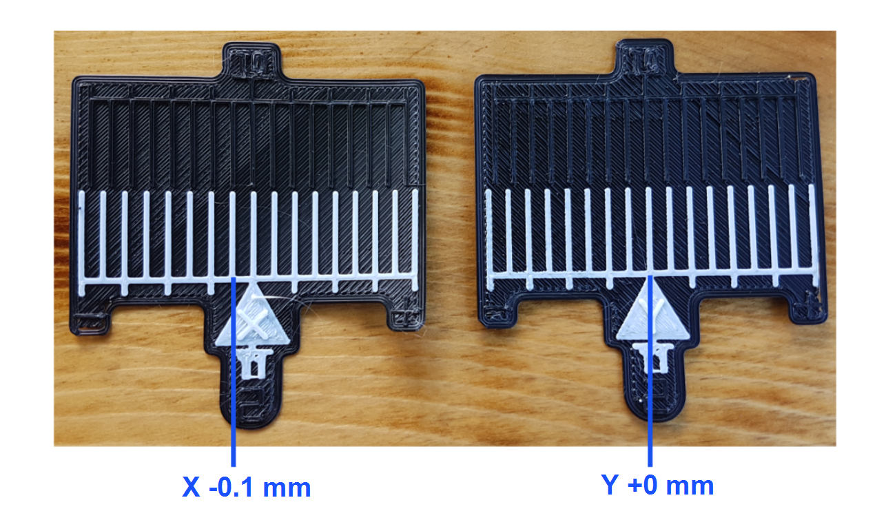
Second X/Y Calibration Attempt
- The second printed scale gives the information that follows:
- X-axis: The T0 and T1 lines align at one line to the left (negative value) from the point of origin (T0).
- The formula is as follows: -0.1 x 1 = -0.1 offset is necessary on the T1 X-axis.
- Y-axis:
- The T0 and T1 lines align at the point of origin (T0).
- The formula is as follows: (0.1 x 0) = 0 offset necessary on the T1 Y-axis. The Y-axis offset value remains the same, and is now correctly calibrated.
- The formula is as follows: (0.1 x 0) = 0 offset necessary on the T1 Y-axis. The Y-axis offset value remains the same, and is now correctly calibrated.
- X-axis: The T0 and T1 lines align at one line to the left (negative value) from the point of origin (T0).
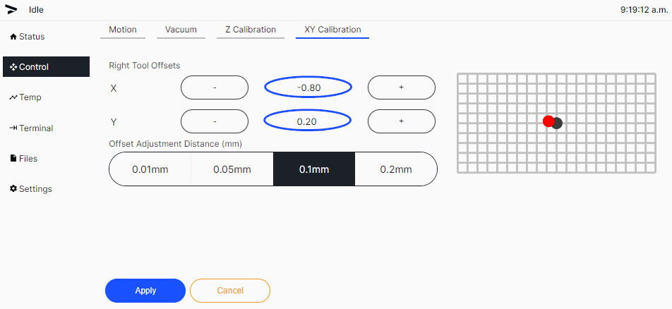
- Select Control > XY Calibration.
- Use the
-button the change the input value to-0.8on the X-axis. - Save the offsets:
- Select
SAVEto save the offsets on the Klipper-based firmware. - Select
Applyto save the offsets on the Marlin-based firmware.
- Select
- Print the same calibration .gcode file a third time.
Third X/Y Calibration Attempt
- The third printed scale gives the information that follows:
- X-axis: The T1 tool has printed 0.0 when compared to T0.
- Y-axis: The T1 tool has printed 0.0 when compared to T0.
- Adjustments are no longer necessary at this point.
