Filament Dry Storage and Feed System Installation
| Model | [•] AON M2+ (CE) | [•] AON M2+ (R-NZ) | [•] AON M2+ | [•] AON-M2 2020 | [•] AON-M2 |
| Category | [•] Installation | [ ] Operation | [ ] Maintenance |
Summary
The procedure that follows gives instructions on how to install the Filament Dry Storage and Feed System (dry box) assembly onto the AON3D machine.
Estimated time: 60-90 minutes
Two Filament Dry Storage and Feed Systems (dry boxes) can be installed on the all machine models. The AON M2+ (CE) comes with the Filament Dry Storage and Feed System installed.
The advantages of a Filament Dry Storage and Feed System (dry box) is as follows:
• Helps keep the filament clean.
• Helps keep the filament in a dry enclosure.
• Helps control the level of humidity in the filament (with the use of desiccant pouches).
For more information on the importance of filament moisture control, refer to Filament Drying and Moisture Control.
To install the spool holders, refer to Spool Holder Installation.
Tools
| Qty | Description | Specification |
|---|---|---|
| 1 | Hex Key | 4 mm |
| 1 | Hex Key | 3 mm |
Parts Information
| Qty | Part Number | Description |
|---|---|---|
| 1 | A-0905-001 | Filament Dry Storage and Feed System (Dry Box) |
| 1 | . P-0905-001 | Backplate, Dry Box Enclosure |
| 1 | . P-0905-002 | Enclosure, Dry Box |
| 1 | . P-0905-003 | Bracket, Dry Box Side |
| 1 | . P-0905-004 | Bracket, Machine Side |
| 1 | . P-0905-005 | Feed Tube, Filament (762 mm/30 in) |
| 1 | . P-0905-006 | Feed Tube, Filament (150 mm/6 in) |
| 1 | . 2E6226F6 | End Cap, Dry Box Spindle |
| 2 | . 3F798770 | Fitting, Bulkhead Union, Tube (6 mm) |
| 1 | . 71CA1286 | Spindle, Dry Box |
| 2 | . 868BE1BE | Foot, Adjustable Low-Profile, Dry Box |
| 1 | . 919B30F4 | Collar, Dry Box Spindle |
| 2 | . 931A1782 | Dry Box Plug (6 mm) |
| 1 | . CAAA0622 | Screw Connection, Dry Box |
| 4 | . HW-BHCS-M5-10 | Screws, Dry Box Enclosure |
| A/R | C-000001 | Molecular Sieve Desiccant 4A - 2/Pk (300g) |
Reach out to our Customer Success team at help@aon3d.com for genuine AON3D replacement part(s) inquiries.
AON3D recommends that one Filament Dry Storage and Feed System (dry box) be installed for each toolhead.
The Filament Dry Storage and Feed System (dry box) can have an opaque or a transparent lid.
Personal Protective Equipment
| Qty | Description | Minimum Specification |
|---|---|---|
| 1 | Safety Eyewear | ANSI/ISEA Z87.1 |
| 1 | Safety Footwear | EN ISO 20345 or ASTM F2413 |
| A/R | Nitrile Gloves | ISO 2859-1 or ASTM D6319 |
Prepare the Machine
- Remove the filament from the extruder(s) and feed path(s). Refer to Replace Filament.
- Push the E-stop button.
- Turn the power OFF with the ON/OFF switch found on the rear panel of the machine.
-
- For AON M2+ (CE) machines: Disconnect power to the machine from the local supply disconnecting device.
- For AON M2+ (R-NZ), AON M2+, AON-M2 2020 and AON-M2 machines: Disconnect the main power cord from the receptacle.
- Wait until the build chamber, bed and hot ends are at room temperature.
Inspect the Dry Box Enclosure Components
- Open the dry box package and make sure that the components that follow are present:
- One enclosure, dry box
- One backplate, dry box enclosure (pre-installed in the dry box enclosure)
- One bracket, dry box side (pre-installed on the dry box enclosure)
- One spindle, dry box (pre-installed in the dry box enclosure)
- One collar, dry box spindle (pre-installed on the dry box spindle)
- One end cap, dry box spindle (pre-installed in the dry box spindle)
- One bracket, machine side
- One feed tube, filament (762 mm/30 in)
- One feed tube, filament (150 mm/6 in)
- Two fitting, bulkhead union, tube (6 mm)
- Two foot, adjustable low-profile, dry box
- Two dry box fitting plug (6 mm)
- One screw connection, dry box
- Four screws, dry box enclosure.
Remove the Filament Spool and Filament Spool Holders
Wait until all machine components are at room temperature before you continue. Some machine components can be hot if the machine was recently used. Failure to do so can cause injuries.
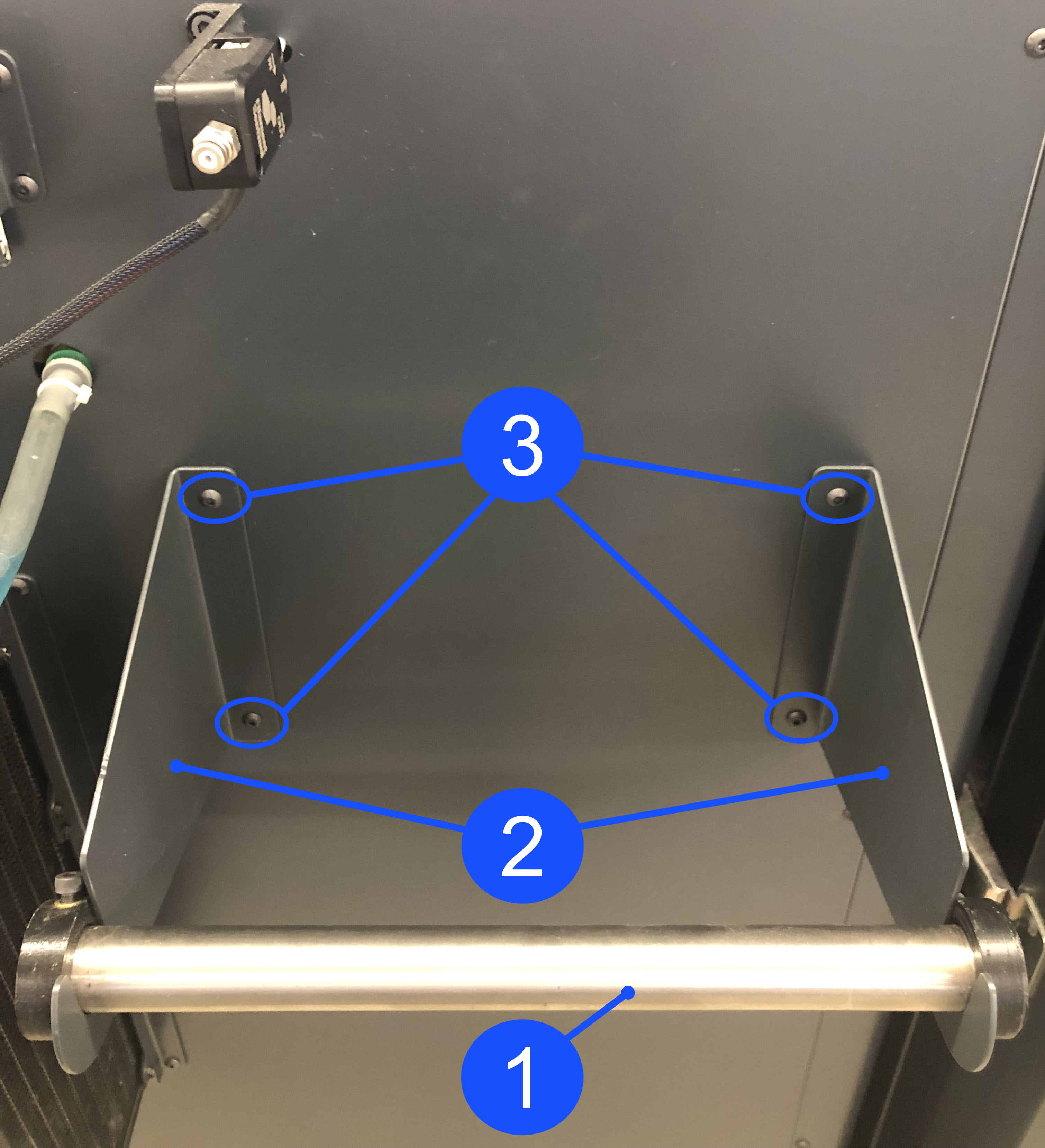
- Lift up the filament spool and remove the spool holder tube (1).
- Set the filament spool and the spool holder tube (1) aside.
- Use the 3 mm hex key to remove the four screws (3) that hold the two spool holder brackets (2).
- Set the two spool holder brackets (2) and the four screws (3) aside.
- Do steps 1 and 2 for the adjacent side, if necessary.
Install the Machine and Dry Box Brackets
Install the Machine Bracket
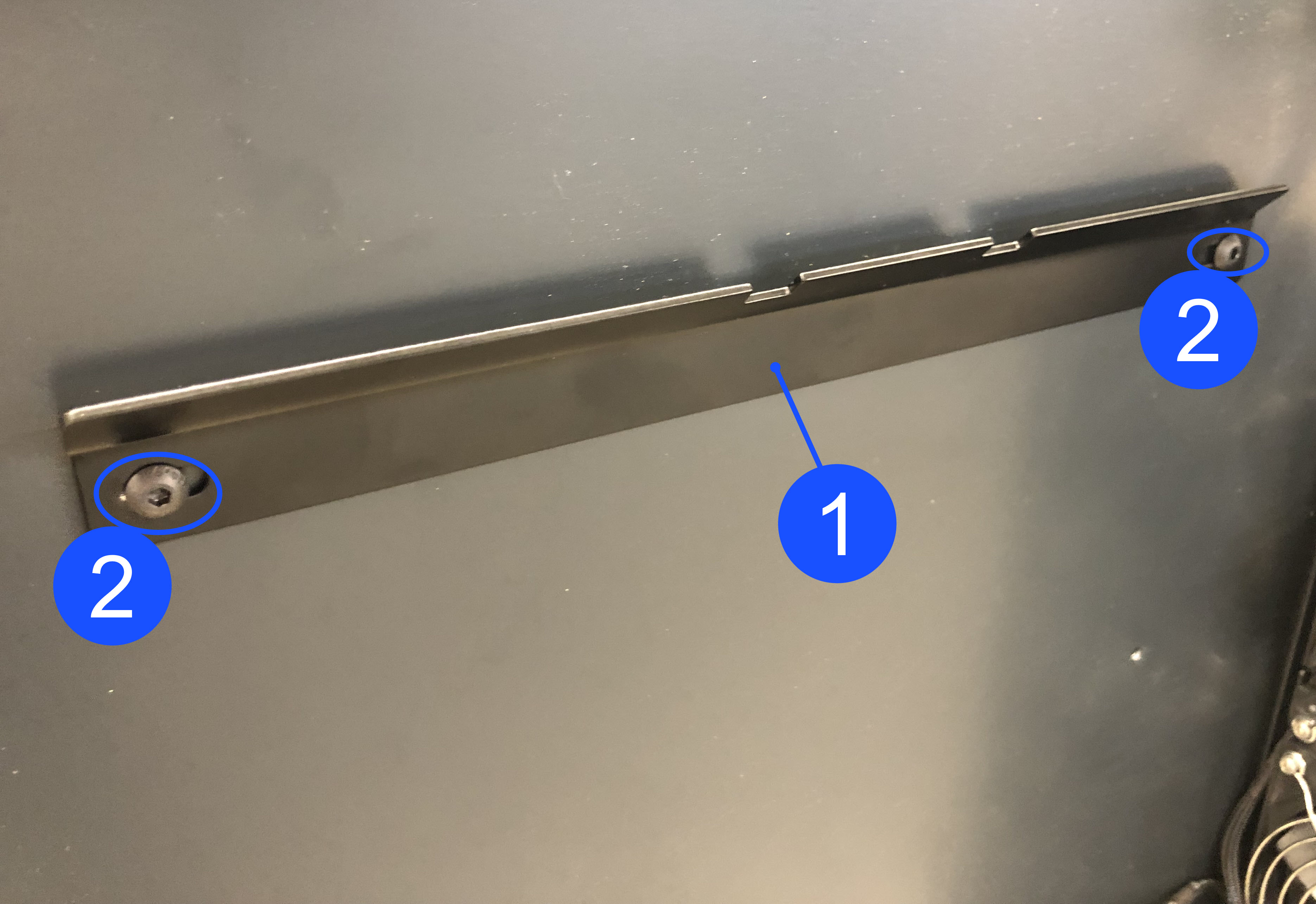
- Install the machine hanger bracket (1) onto the rear machine panel as follows:
- Align the machine hanger bracket (1) holes to the two top holes that were used to hold the two spool holder brackets. Make sure that the bend of machine hanger bracket (1) points UP.
- Manually install the two screws (2) through the machine hanger bracket (1) and into the two top holes of rear panel of the machine.
- Use the 3 mm hex key to tighten the two screws (2). Make sure that the two screws (2) are tight.
- Do steps 1 and 2 for the adjacent machine hanger bracket (1), if necessary.
Install the Dry Box Enclosure Assemblies
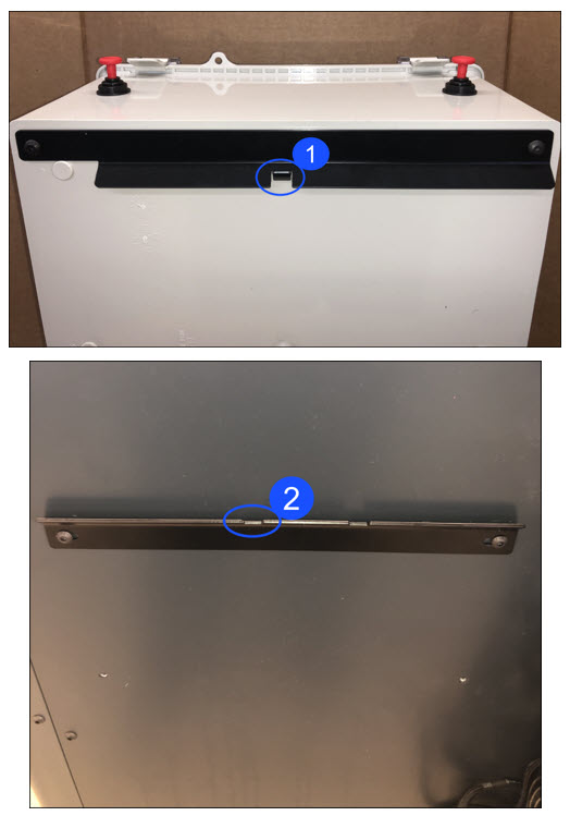
- Carefully install the dry box enclosure assembly onto the machine hanger bracket.
- Make sure that the dry box hanger bracket tab (1) and the notch on machine hanger bracket notch (2) engage correctly.
- Do steps 1 and 2 to install a dry box enclosure assembly for the adjacent toolhead, if necessary.
Prepare the Dry Box Enclosure Assembly
Prepare the Dry Box Enclosure for T0 Operation
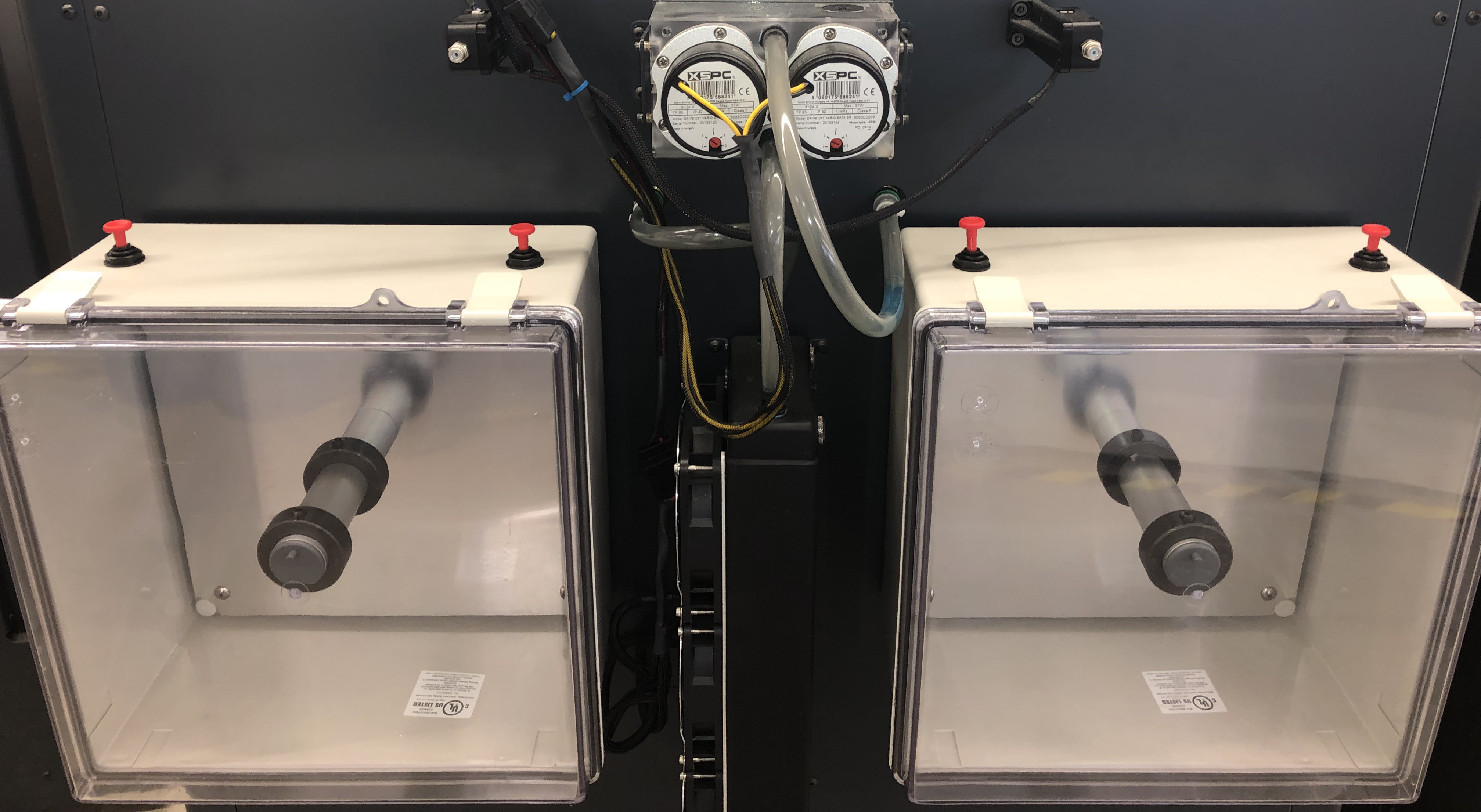
When the machine is viewed from the rear, the dry box enclosure on the LEFT must feed the RIGHT toolhead (T0). Failure to do so can cause print failures and/or damage to machine component(s).
When the machine is viewed from the rear, do the steps that follow for the LEFT dry box assembly:
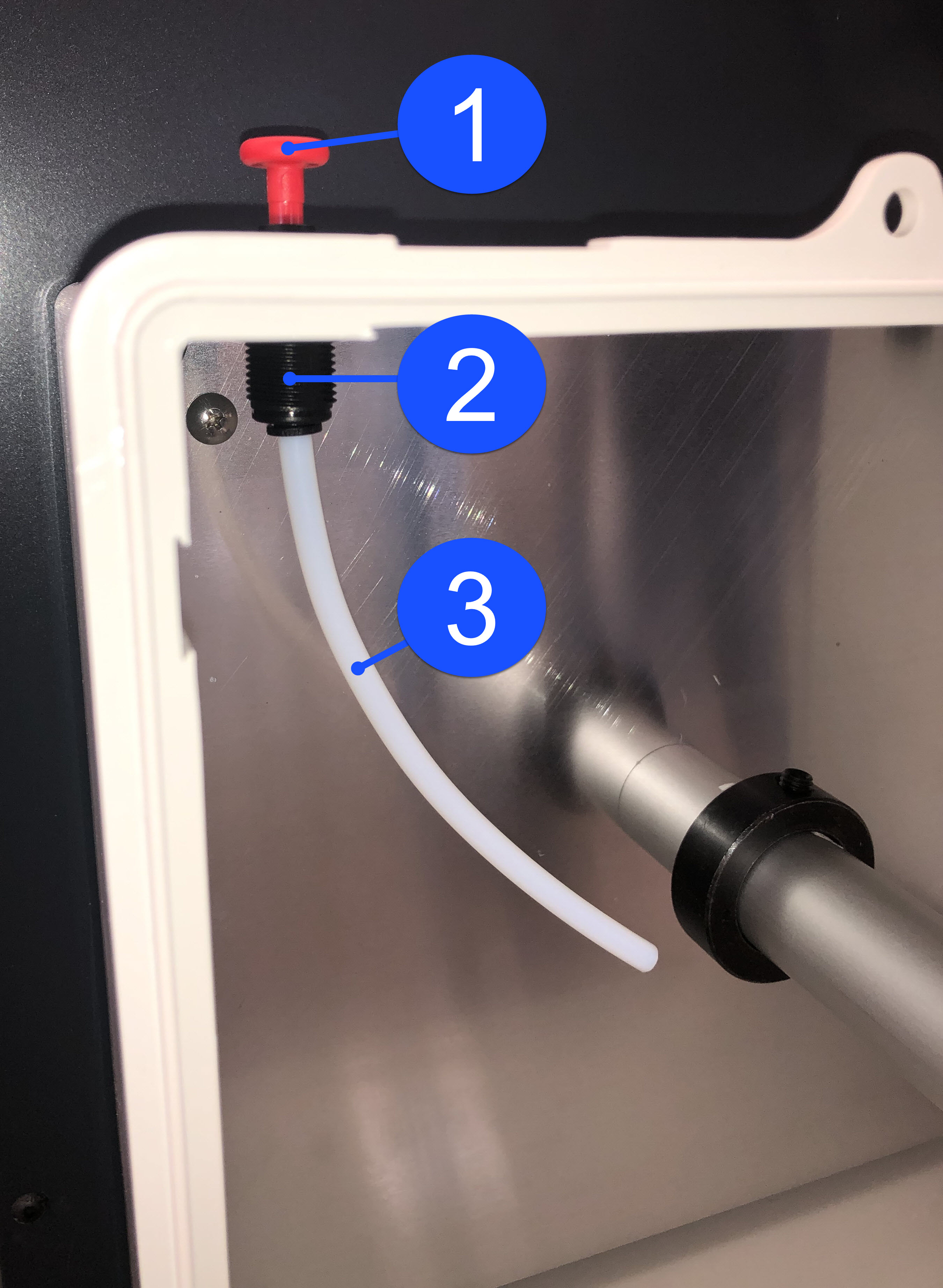
- Remove the plug (1) that is installed in the top LEFT dry box feed tube fitting (2).
- Open the lid to the LEFT dry box enclosure.
- Push the new 150 mm (6 in) feed tube (3) in the bottom of the LEFT dry box feed tube fitting (2).
- Lightly pull on the 150 mm (6 in) internal feed tube (3) to make sure it is correctly installed in the dry box feed tube fitting (2).
- Push the 762 mm (30 in) feed tube (4) into the top of the LEFT dry box feed tube fitting (5). Lightly pull on the 762 mm (30 in) feed tube (4) to make sure it is correctly installed in the dry box feed tube fitting (5).
- Push the other end of the 762 mm (30 in) feed tube into the RIGHT (T0) filament sensor fitting (6). Lightly pull on the 762 mm (30 in) feed tube to make sure it is correctly installed in the filament sensor fitting (6).
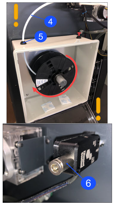
Reach out to our Customer Success team at help@aon3d.com about SB-2020-03 if the filament sensor fitting does not have the correct feed tube diameter.
Prepare the Dry Box Enclosure for T1 Operation
When the machine is viewed from the rear, the dry box enclosure on the RIGHT must feed the LEFT toolhead (T1). Failure to do so can cause print failures and/or damage to machine component(s).
When the machine is viewed from the rear, do the steps that follow for the RIGHT dry box assembly:
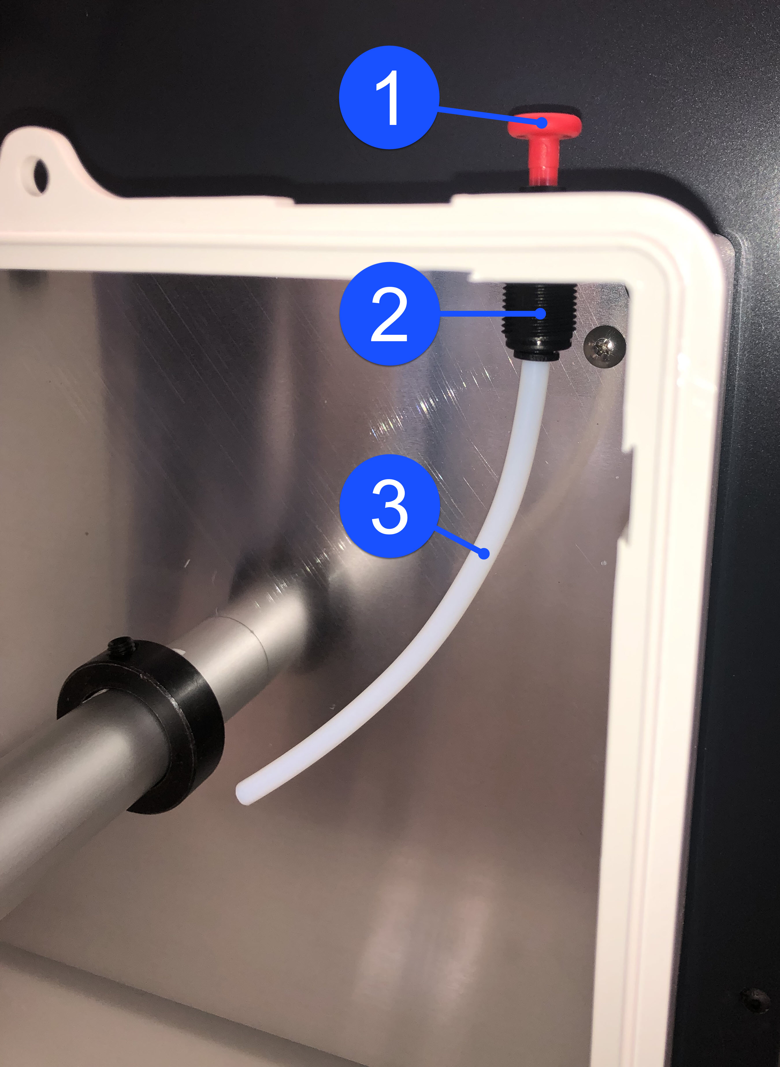
- Remove the plug (1) that is installed in the top RIGHT dry box feed tube fitting (2).
- Open the lid to the RIGHT dry box enclosure.
- Push the new 150 mm (6 in) feed tube (3) in the bottom of the RIGHT dry box feed tube fitting (2). Lightly pull on the 150 mm (6 in) internal feed tube (3) to make sure it is correctly installed in the dry box feed tube fitting (2).
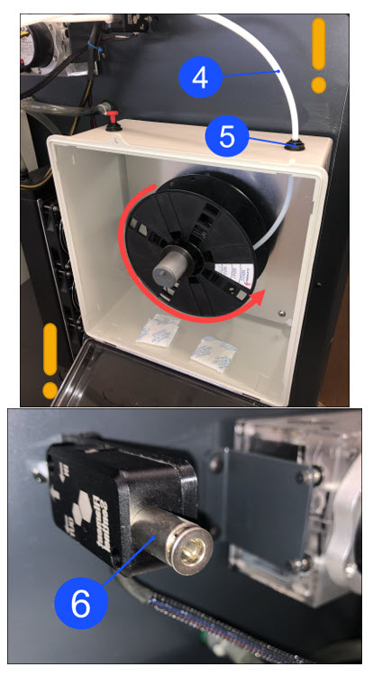
- Push the 762 mm (30 in) feed tube (4) into the top of the RIGHT dry box feed tube fitting (5). Lightly pull on the 762 mm (30 in) feed tube (4) to make sure it is correctly installed in the dry box feed tube fitting (5).
- Push the other end of the 762 mm (30 in) feed tube into the LEFT (T1) filament sensor fitting (6). Lightly pull on the 762 mm (30 in) feed tube to make sure it is correctly installed in the filament sensor fitting (6).
Reach out to our Customer Success team at help@aon3d.com about SB-2020-03 if the filament sensor fitting does not have the correct feed tube diameter.
Install the Roll of Filament
Refer to the Load Filament procedure.
Test and Return To Service
-
- For AON M2+ (CE) machines: Connect power to the machine from the local supply disconnecting device.
- For AON M2+ (R-NZ), AON M2+, AON-M2 2020 and AON-M2 machines: Connect the main power cord to the receptacle.
- Turn the power ON with the ON/OFF switch found on the rear panel of the machine.
- Release the E-stop button.
- Home XYZ.