Quick Start (Marlin)
The following guide provides a high-level order of operations to ensure ongoing success with the AON M2+ (CE), AON M2+ (R-NZ) and AON M2+ machines that have the Marlin-based firmware. Make sure that all linked articles are read in their entirety as this section is only meant to serve as a quick start overview.
The instructions that follow are for the AON M2+ (CE), AON M2+ (R-NZ) and AON M2+ machines that have the Marlin-based firmware only.
Refer to Quick Start Klipper AON M2+ (CE), AON M2+ (R-NZ) and AON M2+ machines that have the Klipper-based firmware.
- 1. Basic System Setup and Preparation
- 2. Calibration
- 3. Run the G-Code
1. Basic System Setup and Preparation
1.1. Clean the Machine
- Make sure that the machine is clean and that there is no unwanted material(s) around the lead screws and/or around the linear guides and guide rails.
- Make sure that the nozzle is clean. Use the wire brush to clean the nozzle while it is set above the material’s glass transition temperature (Tg).
- Make sure that the print surface is clean and free of solvents and/or unwanted materials.
Refer to Clean Build Platform and Build Chamber.
Do not use compressed air to clean the machine component(s) unless otherwise specified. The use of compressed air can cause damages to machine component(s).
1.2. Load/Replace Filament
Make sure there is sufficient filament on the spool before a print is started. Simplify3D® gives an estimate on the weight of filament necessary for each part in the G-Code viewer. To calculate the weight of filament necessary:
- Weigh the spool of filament to be used.
- Subtract the weight of an empty spool from the weight of the spool of filament to be used.
- Compare the above results to the estimated weight in Simplify3D®.
- Refer to the Load Filament procedure.
- Refer to the Replace Filament procedure.
Make sure that the filament density in Simplify3D® is entered correctly. In Simplify3D®, select Edit Process Settings > Other.
1.3. Prepare Heater Block Assembly
Install the heater block assembly that has a nozzle size that matches your print profile. Refer to Replace Heater Block Assemblies.
1.3.1. Heat the Heater Block Assembly to Extrusion Temperature
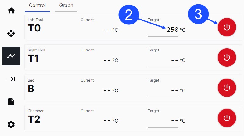
Use the Graphical User Interface (GUI), or web browser, to heat the toolhead(s) to the extrusion target temperature for the chosen material:
- Select Temp.
- For T0, enter the target temperature in the field under Target.
- Select the ON/OFF icon to power ON the T0 heater.
- Do steps 1 to 3 for the adjacent toolhead, if necessary.
1.3.2. Purge Filament
Do not touch the hot ends when the toolhead heater(s) are active. The temperatures in the hot end(s) range from 200°C to 500°C (390°F to 932°F) and will result in injury when touched.
- Make sure the hot end is at the correct target temperature.
- Found on top of each extruder body is a tab (1) and a lever (2):
- Compress the tab (1) and lever (2) together with light finger pressure to temporarily lock the internal gears apart and let filament pass through.
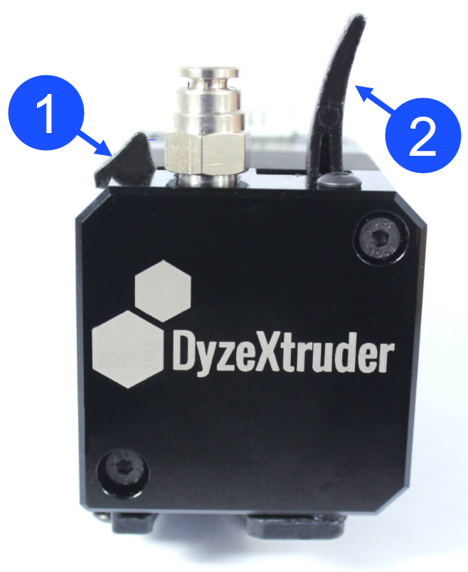
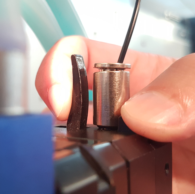
- Compress the tab (1) and lever (2) together with light finger pressure to temporarily lock the internal gears apart and let filament pass through.
- Manually put the filament in the extruder, and carefully push it down into the hot end until it extrudes from the nozzle.
Do not push the filament too hard through the extruder assembly. This can cause a restriction in the feed path, and/or, cause damage to machine component(s).
- After the filament has been successfully extruded from the nozzle, compress the extruder tab (1) and lever (2) to release the locking mechanism and engage the extruder drive gears onto the filament. When the extruder drive gears are engaged, the filament cannot be manually pulled from the extruder.
- Install the PTFE tube into the extruder fitting.
- On the GUI, select the Control > Motion.
- Select the Left Tool, set the Extrusion Distance (mm) to
100and set the Extrusion Speed (mm/sec) to5.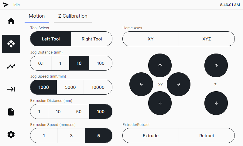
- Select
Extrudetwo times to feed 200 mm of the filament through the hot end. Filament will now be extruded from the nozzle. - Do steps 1 to 8 for the adjacent toolhead, if necessary.
1.3.3. Retract Hot End Filament
Filament must be retracted from the AON M2+ (CE), AON M2+ (R-NZ), and AON M2+ hot end assembly(ies) when there is no print in progress.
Use of the GUI/web browser to perform a retraction of 20 mm.
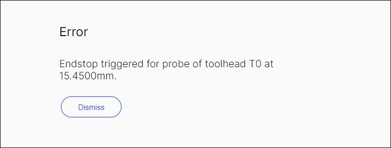
Failure to retract the filament from the hot end(s) can signal the GUI to give an error message.
Turn the power to hot end heater(s) OFF when there is no print in progress. Do not let the hot end heater(s) idle for an extended period of time without extrusion. This can cause the polymer filament to burn and clog the nozzle(s). Refer to Hot End Heater Timeout Feature.
1.4. Prepare the Build Platform
1.4.1. Select the Build Platform
Refer to the Build Platform Adhesion guide to determine a compatible build platform.
1.4.3. Apply Adhesion Aid
Some filament and build platform combinations require the use of an adhesion aid.
- The Nano Polymer Adhesive can be applied to increase build platform adhesion.
- The Nano Polymer Adhesive can be used as a release agent to facilitate part removal without damaging the part and/or PEI build sheet.
1.4.2. Install Build Platform Start Vacuum Bed Feature
The build platform must be correctly installed to get satisfactory print results.
- For the AON M2+ (CE), AON M2+ (R-NZ),and AON M2+ machines: Refer to the Install Build Sheet procedure.
- For the AON-M2 2020 and AON-M2 machines: Refer to the Install Build Plate procedure.
The AON M2+ (CE), AON M2+ (R-NZ), and AON M2+ machines have the Vacuum Bed Feature. Refer to Vacuum Bed Feature.
1.5. Preheat Machine Components
1.5.1. Preheat Build Chamber and Bed
Use the Graphical User Interface (GUI) to heat the bed and chamber target temperatures for the chosen material:
- Select Temp.
- For the bed, enter the bed temperature in the field under Target.
- Select the ON/OFF icon to power ON the
Bheater. - For the chamber, enter the chamber temperature in the field under Target.
- Select the ON/OFF icon to power ON the
T2heater.
1.5.2. Wait for Thermal Equilibrium (Heat Soak)
Refer to Preheat Build Chamber Components.
2. Calibration
2.1. Heat the Heater Block Assembly to Bed Temperature
Use the Graphical User Interface (GUI) to heat the toolhead(s) to the extrusion target temperature for the chosen material:
- Select Temp.
- For T0, enter the bed temperature in the field under Target.
- Select the ON/OFF icon to power ON the
T0heater. - Do steps 1 to 3 for the adjacent toolhead, if necessary.
2.2. Calibrate the Z-Axis
AON3D recommends calibrating the Z-axis before every print.
2.2.1. Start the Probing Sequence
Refer to the Calibration Index to select the correct calibration procedure for your machine:
- For the AON M2+ (CE), AON M2+ (R-NZ), and AON M2+ machines, refer to the Z Offset Calibration (M2+) procedure.
- For the AON-M2 2020 and AON-M2 machines, refer to the Z Offset Calibration procedure.
2.2.2. Set the Z-Axis Offset
- Select Tool Adjustment Distance, and select
0.1mmor0.05mmincrement. - Under Adjust Printing, select
FartherorCloserto adjust the distance between the build platform and the nozzle.- Select
Fartherto move the build platform down (away from the nozzle). - Select
Closerto move the build platform up (toward the nozzle).Make sure to give the Z-axis the time necessary to move in the selected direction.
Make sure the flex probe is not compressed at this point. This can occur if the Z offset is set too near to the build platform. To prevent toolhead collision(s), keep a small distance between the nozzle and build platform.
- Select
- Make sure that the nozzle does not touch the build platform. If the nozzle touches the build platform, select
0.1mm, then selectFartheruntil there is a distance between the nozzle and the build platform. - Select the
FartherandCloserbuttons to adjust the Z offset until the nozzle is approximately 0.1 mm from the build platform.
2.2.3. Save Z-Axis Offset with M500
Use the Graphical User Interface (GUI)/web browser as follows:
- Select Settings > Terminal.
- Input the
M500command to save the offset. - Let the machine run the command.
2.3.4. Set the Z-Axis Offset for T1
- Do steps 2.2.1 to 2.2.3 for the adjacent toolhead, if required.
2.3. Calibrate X/Y Toolhead Offsets
If a print uses the two toolheads for the same print, the toolheads must be calibrated along the X/Y-axes before a print is started. The X/Y-axes calibration procedure adjusts the coordinate system of the two toolheads to be in line with each other.
2.3.1. Print X/Y Calibration - 0.1 mm Scale
To make sure that the X/Y Toolhead Offsets Calibration procedure is done correctly, AON3D provides STL files.
Refer to the X/Y Toolhead Offsets Calibration procedure.
2.3.2. Enter Correction Factor
When the print is complete:
- Open the build chamber door.
- Use the parts removal tool to remove the printed scale from the build print surface.
- Close the build chamber door so as to not let the build chamber temperature decrease.
- Examine the lines to calculate the necessary T1 offset(s) to align the two toolheads.
- Select Control > XY Calibration.
- Select
0.1mmas theOffset Adjustment Distance (mm). - Use the
-or+button to input the offset value on the X-axis. - Use the
-or+button to input the offset value on the Y-axis. - Select
Applyto save the offsets.
2.3.3. Re-Print 2 to 3 Times
Repeat the X/Y calibration - 0.1 scale print and adjust the X/Y Toolhead Offsets until the X-axis and Y-axis scales center lines are aligned.
3. Run the G-Code
3.1. Load G-Code File Through Web Browser
To upload a file into the GUI:
- On the web browser, select Files.
- Select
Upload Files, and import the G-code file onto the AON3D machine.
3.2. Heat the Heater Block Assembly to Extrusion Temperature
Heat the heater block assembly to the necessary extrusion temperatures before a print is started.
3.3. Start the Print
- On the GUI/web browser, select Files.
- Select
Printon the file to print. - Select
Printto confirm.
3.4. Evaluate the First Layer and Live Adjust Z-Axis Offset
- Make sure that the quality of the first layer height is correct before a print can continue.
- The Z offset calibration can be adjusted in minute increments to help get the correct first layer:
- Select Tool Adjustment Distance, and select
0.1mmor0.05mmincrement. - Under Adjust Printing, select
FartherorCloserto adjust the distance between the build platform and the nozzle.- Select
Fartherto move the build platform down (away from the nozzle). - Select
Closerto move the build platform up (toward the nozzle).
- Select
- Select Tool Adjustment Distance, and select