First Layer Guide
| Model | [•] AON M2+ (CE) | [•] AON M2+ (R-NZ) | [•] AON M2+ | [•] AON-M2 2020 | [•] AON-M2 |
| Category | [ ] Installation | [•] Operation | [ ] Maintenance |
Summary
The first layer is essential for every Fused Filament Fabrication (FFF) 3D print, as it forms the foundation for the part to be printed. If the first layer does not stick to the build platform correctly, the part can move before it is completed, which will lead to a failed print.
The first layer adhesion also affects how easily the part will be removed from the build platform when the print is completed. For build platform-specific recommendations, refer to the Build Platform Adhesion guide.
Z Offset Adjustment
The user must complete the Z offset calibration before a first layer can be successfully printed.
- For the AON M2+ (CE), AON M2+ (R-NZ) and AON M2+ machines that operates the Klipper-based firmware, refer to the Z Offset Calibration (M2+ Klipper) procedure.
- For the AON M2+ (CE), AON M2+ (R-NZ) and AON M2+ machines that operates the Marlin-based firmware, refer to the Z Offset Calibration (M2+ Marlin) procedure.
- For the AON-M2 2020 and AON-M2 machines, refer to the Z Offset Calibration procedure.
The Z offset must be adjusted during first layer. This can be done when a skirt, brim or raft is in progress.
- On the GUI/web browser, select Files > Print to start a print.
- Select the Control > Z Calibration.
- Select the
0.05 mmor0.01 mmincrement to adjust the Z offset. - Select the
FartherandCloserbuttons to adjust the Z offset height at the start of the print.- Make sure to give the machine the time necessary to register the command.
- Examine the layer and adjust the Z offset as necessary.
- Do steps 3 and 5 for the while the adjacent toolhead is active.
First Layer Offset Examples
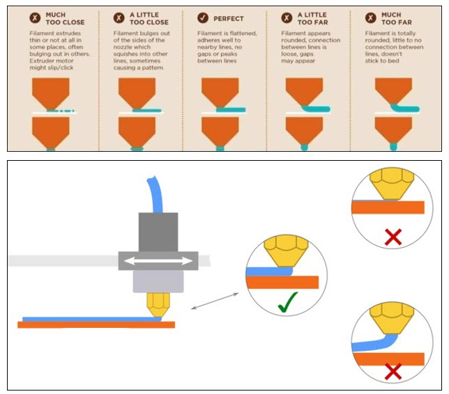
The Z offset controls the nozzle spacing in relation to the build platform. Appropriate spacing is required to ensure that the first printed layers adheres to the build platform. By controlling the nozzle-to-bed distance, the effective contact area of the print to the build platform can be adjusted. An appropriate distance may prevent the material accumulation at the nozzle, reducing potential toolhead collisions.
Generally, decreasing the nozzle-to-bed distance increase first layer adhesion and vice-versa. Minutes adjustments may be needed while printing the first layer. It may ensure an appropriate distance, correcting for uncertainties in nozzle spacing experienced with the machine.
Refer to the information that follows to get a reference of what to look for in the first layer print.
Z Offset Value Is Too Small
A print with the Z offset being too small, ie. the bed is too close to the nozzle will be as follows.
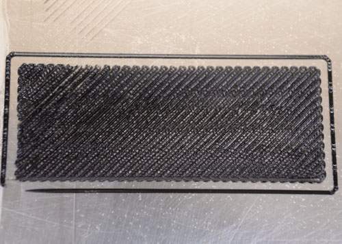
The extruded bead may become overly constrained by neighboring extrusions. This can result in deposited material being ejected beyond the toolhead path of the nozzle tip. Three failure types may occur:
-
Immediate layer failure occur with an accumulation of material around the nozzle tip. Spacing is too close, causing the dislodgement of neighboring extrusions as new extrusions are being placed.
-
Protrusion of material creates a collision risk with the toolhead. Collision between the toolhead and part may result in layer shifting with part and/or toolhead damage.
-
Very close spacing may cause increased heat exposure of the first layer and underlying build platform. The first layer of the part and build platform may be welded, making part removal impossible.
Select Farther to move the print surface away from the nozzle, in small increments.
Z Offset Value Is Too Large
A print with the Z offset being too big, ie. the bed is too far from the nozzle will be as follows.
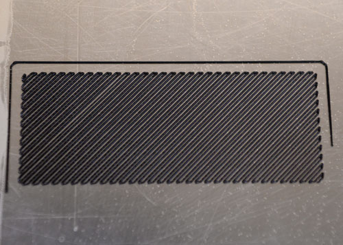
Not enough material will be in contact with the build platform. The amount of extruded material being forced into the asperities of the build platform may be reduced if the nozzle-to-bed distance is too big. The lack of surface area and interlocking of bodies may reduce the first layer adhesion to the build platform.
Select Closer to move the print surface towards the nozzle, in small increments.
Z Offset is Adequate
A print with a perfectly adjusted Z offset will be as follows.
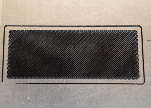
Adjacent extrusions a somewhat deformed by confinement between the print surface and the nozzle surface. Optimal bonding with the neighboring extrusions as each pass is deposited may occur as they are deformed into rectangular/elliptical sections.