Layer Tab
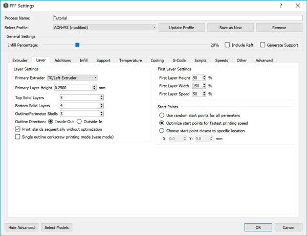
Primary Extruder
The Primary Extruder in this tab is the toolhead that is used to print the shell of the model. This includes the surface and top and bottom layers.
Whichever toolhead you’re loading the main model material into should be selected. You may choose to print the shell in one material and the infill in a different material for example, or shell and infill in one material with support material using the other toolhead. In general, we recommend you get in the habit of using T0/Left Extruder as your primary toolhead as all support documentation is written with this configuration.
Primary Layer Height
Primary Layer Height sets the thickness of each printed layer.
We recommend 0.20-0.25mm as the nominal working value as it provides the best balance between print time and visual quality. 0.15mm is recommended for fine work, 0.10mm for superfine work, and up to 0.4mm for rough iterations or parts where the highest strength is desired over surface finish or tight-toleranced fit. Although the AON-M2 is capable of layer heights below 0.05mm, our experience has shown that the improvement in surface finish below 0.10mm to be negligible while increasing print times drastically and requiring extremely fine tuning of the process settings to be successful.
We do not recommend a layer height that is more than half the value of the Extrusion Width as layer bonding and overall part strength decreases as a result of the narrow extrusion bead profile.
Top/Bottom Solid Layers
This value is number of layers on the top/bottom surface of a part to print with 100% density.
There are two considerations in choosing the correct value for these settings. One is part strength - if the shell thickness needs to be a certain minimum value, it must be achieved by multiplying the layer height by the number of Top/Bottom Solid Layers. The other is surface finish, especially for the Top Solid Layers - a low Infill Percentage combined with a low number of Top Solid Layers will result in a top layer that is not solid since the fill must bridge over the gaps created by the sparse infill.
In general, an infill greater than 20% will be sufficiently covered by a minimum of 3 Top Solid Layers when using a Layer Height greater than 0.20mm. Smaller Layer Heights and sparser Infill Percentages will require more Top Solid Layers.
Outline/Perimeter Shells
The number of extrusion passes that will be used to create the shell, or outer surface of the part.
If engineering calls for a specified wall thickness value, you must multiply the Extrusion Width by the number of Shells to achieve the wall thickness. A minimum of 2 shells is recommended at all times - fewer than 2 with typical extrusion widths often results in poorer surface finish as the infill printing movements perturb the outer shell, resulting in visible vertical line artifacts on the print surface.
An uncommon piece of knowledge is that increasing the number of Shells increases part strength more than increasing the Infill Percentage with respect to the increase in material usage and print time under most loading conditions.
Outline Direction
When printing the shell, this determines if the multiple passes start from the inside and print outwards, or vice-versa.
Inside-out results in a slight increase in mechanical properties, while outside-in may give a slight increase in surface finish quality.
Inside-out printing
Outside-in printing
Print Islands Sequentially
If your model contains “islands” (ie. non-contiguous printing areas), turning this option off will optimize for print speed by minimizing the amount of travel moves.
For example, given two print areas A and B, optimization will print
A > B > Layer Change > B > A
while without optimization, it will print
A > B > Layer Change > A > B
The consequence of optimization is that you are at risk of dumping too much heat into the part, causing deformation. Non-optimization allows time for the freshly printed layer to cool while the toolhead is printing elsewhere.
We recommend you always keep this option turned on - the marginal increase in print time is not worth the consequences for print quality, especially given the rapid travel speeds of the AON-M2.
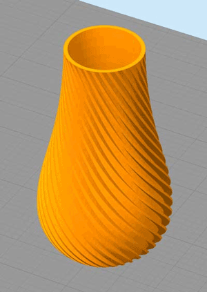
Single Outline
For certain models under specific circumstances, you are able to use “Vase Mode” to print a hollow model with one continuous toolpath. With no layer changing discontinuities, you can achieve a seamless print with perfect surface finish. However, you can only print with a single perimeter, no infill, no supports, and an open top surface unless your model naturally narrows to a point.
To use vase mode, your model must:
- Be modeled as a solid, not a hollow object. Due to nature of STL files, all surfaces in the model must be processed by the slicer and the slicer cannot “detect” which is meant to be the inner or outer surface.
- Have no internal gaps, ie. you can trace the outline with one continuous line.
This model is not compatible with vase mode as the internal hollow has been modeled into the actual STL.
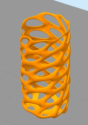
This model is not compatible with vase mode since it fails the continuous outline test.
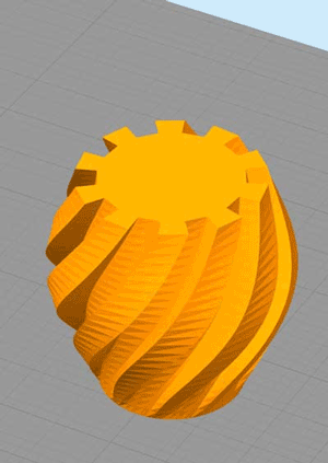
This model is compatible with vase mode.
First Layer Settings
These settings override the primary settings for the first layer of the print. If you are having trouble getting a part to stick to the bed, these settings can help.
First Layer Height
This setting overrides the Primary Layer Height only for the first layer of the print, and behaves differently depending on if the value is greater or less than 100%.
When the value is set to <100%, the physical Z-height (ie. the distance between the nozzle and the bed) decreases, but the extrusion rate remains unchanged, resulting in the first layer overextruding and being “squished” down into the bed surface. For example, if the Primary Layer Height is 0.25mm and the First Layer Height is set to 80%, the first layer will be 0.2mm from the bed, while extruding as much material as if it were still printing a 0.25mm layer thickness.
When the value is set to >100%, the physical Z-height increases, and the extrusion rate also increases correspondingly, resulting in an overall thicker layer for better adhesion when the Primary Layer Height is small without overextruding. For example, if the Primary Layer Height is 0.10mm and the First Layer Height is set to 200%, the first layer will be 0.2mm from the bed, while extruding the amount of material that would be typical for a normal 0.2mm layer thickness.
The ideal setting depends on your Primary Layer Height and Extrusion Width. A thick first layer will greatly help the part stick to the bed. Use a value that will result in a first layer at least 0.2mm thick, up to half the Extrusion Width.
First Layer Width
This overrides the Extrusion Width for only the first layer of the print. A wider, flatter extrusion bead profile provides more contact with the bed surface to increase adherence to the bed.
Generally, set this at 120% except for cases where the Extrusion Width is already set above the Auto value. When the First Layer Height override is set to less than 100%, the extruder is overextruding so a value of 90-95% for the First Layer Width can compensate for this and yield a cleaner print.
First Layer Speed
This overrides the movement speed for only the first layer of the print. A slower print speed will help improve first layer adhesion to the bed.
Generally, you’ll want the first layer to print at a speed of 20-40mm/s for best adhesion. Take your Default Printing Speed and find out what percentage of that value gets you within that range, and put that value in this box.
Start Points
Start Points refer to where the layer change occurs, and thus where the layer change seam will be visible on the surface.
- Use Random Start Points will distribute the start points in random locations.
- Optimize Start Points will pick start points to minimize travel moves
- Choose Start Point will ensure all start points align towards a user-specified co-ordinate on the print bed.
Choose Start Point gives you control over where the seam will be created and is best for when surface finish quality is important - choose a point on the model where the seam will be the least conspicuous. On models with a corner that runs vertically up, this is would be an ideal location. However, aligning all the seams along a straight vertical path creates a point of failure from a part strength perspective.
For the same reasons as above, Random Start Points will be best for part strength at the expense of surface finish quality.
Optimize Start Points provides the best of both worlds and is the recommended default setting.