Replace Y-Axis Idler Pulley Assembly
| Model | [•] AON M2+ (CE) | [•] AON M2+ (R-NZ) | [•] AON M2+ | [•] AON-M2 2020 | [•] AON-M2 |
| Category | [ ] Preventive | [•] Corrective |
Summary
The procedure that follows gives the instructions on how to replace the two Y-axis idler pulley assemblies.
Estimated time: 45 minutes
Tools
| Qty | Description | Specification |
|---|---|---|
| 1 | Hex Key | 4 mm |
| 1 | Wrench | 10 mm |
| A/R | Rags | Lint-free |
| A/R | Isopropyl Alcohol | 99% |
Parts Information
| Qty | Part Number | Description |
|---|---|---|
| 2 | A-0302-003 | Y-Axis Idler Assembly |
Reach out to our Customer Success team at help@aon3d.com for genuine AON3D replacement part(s).
To help with print quality and machine reliability, AON3D recommends to change the two Y-axis idler pulley assemblies as a pair.
Personal Protective Equipment
| Qty | Description | Minimum Specification |
|---|---|---|
| 1 | Safety Eyewear | ANSI/ISEA Z87.1 |
| A/R | Nitrile Gloves | ISO 2859-1 or ASTM D6319 |
Prepare the Machine
Make sure that there are no prints on the build surface. Remove print(s) before the procedure that follows is started. Failure to do so can cause a collision and cause damage to the machine component(s).
- Home XYZ.
- Lower the Z-axis by 300 mm.
- Move the X-gantry to the rear of the build platform.
- Open the build chamber door.
- Push the E-stop button.
- Turn the power OFF with the ON/OFF switch found behind the machine.
-
- For AON M2+ (CE) machines: Disconnect power to the machine from the local supply disconnecting device.
- For AON M2+ (R-NZ), AON M2+, AON-M2 2020 and AON-M2 machines:
Disconnect the main power cord from the receptacle.
Dangerous voltages continue to be found in the electrical panel when the ON/OFF switch is set to OFF. Disconnect the main power cord from the machine while maintenance is done. Failure to do so can cause electric shock.
- Wait until the build chamber, build platform and hot ends are at room temperature.
Remove the Y-Axis Idler Pulley Assemblies
Wait until all the machine components are at room temperature before you continue. Some machine components can be hot if the machine was recently used. Failure to do so can cause injuries.
- Remove the Y-axis idler pulley (3) as follows:
- Use the 10 mm wrench to loosen the jam nut (1).
- Use the 10 mm wrench to loosen the tension screw (2) until there is no tension on the Y-axis belt.
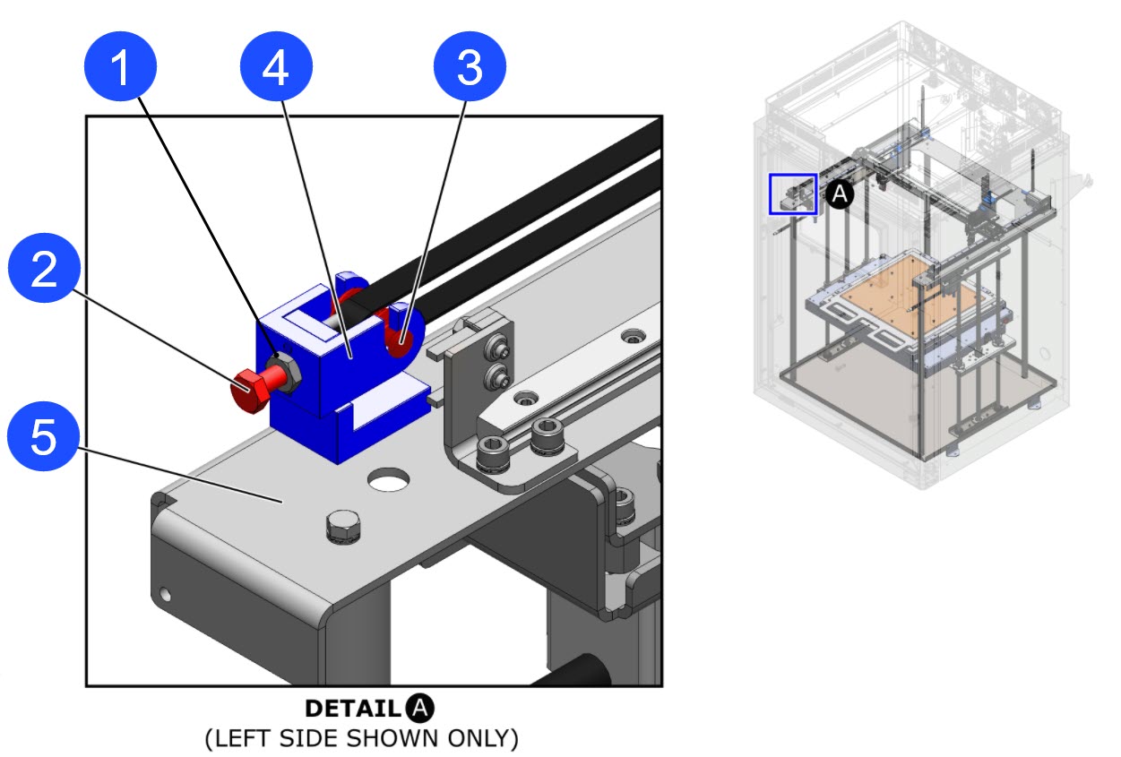
- Pull, lift up, and remove the Y-axis idler pulley (3) from the Y-axis idler pulley assembly (4).
- Remove the Y-axis idler pulley (3) from the Y-axis belt.
- Inspect the Y-axis belt for wear. Replace as necessary. Refer to Replace Y-Axis Belts.
- Use the 4 mm hex key to remove the screw (6) from the Y-axis idler bracket (7).
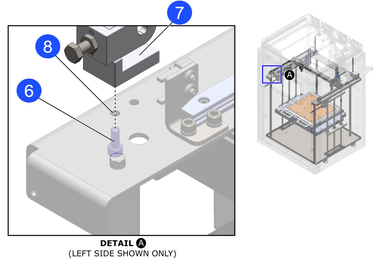
- Remove the Y-axis idler pulley assembly (4) and the Y-axis idler bracket (7) from the machine.
- Discard the Y-axis idler pulley assembly (4) and the Y-axis idler bracket (7).
- Do steps 1 to 4 for the components on the adjacent side, if necessary.
Install the New Y-Axis Idler Pulley Assembly
The Y-axis idler assemblies are symmetrical. The same Y-axis idler assembly can be installed on either the right and/or left side.
- Use a lint-free rag and isopropyl alcohol to clean the Y-axis top plate (5) surface.
- Let the clean surface dry for two minutes.
- Put the Y-axis idler pulley assembly (2) and the Y-axis idler bracket (7) in position onto the Y-axis top plate (5).
- Align the threaded hole in the Y-axis idler bracket (7) with the hole (3) in the Y-axis top plate (5).
- Manually install the screw (6) through the hole (3) in the Y-axis top plate (5), and into the Y-Axis idler bracket (7).
- Make sure that the screw (6) is completely seated on the Y-axis top plate (5). Do not tighten the screw (6) at this point in time.
- Install the new Y-axis idler pulley (3) as follows:
- Put the Y-axis belt in position around the Y-axis idler pulley (3).
Make sure that the Y-axis belt is installed straight, with no twists, no kinks, and/or no loops. Failure to do so will cause irregular print quality and/or will cause damage to the machine component(s).
- Install the Y-axis belt and the Y-axis idler pulley (3) into the Y-Axis idler pulley assembly (4).
Make sure that the Y-axis belt teeth are correctly engaged on the Y-axis idler pulley (3) teeth.
- Manually tighten the tension bolt (2) to apply a light load onto the Y-axis belt. Do not use the 10 mm wrench to tighten the tension bolt (2) at this point in time.
- Put the Y-axis belt in position around the Y-axis idler pulley (3).
- Do the steps that follow to align the Y-Axis idler pulley assembly (4) and the Y-axis idler bracket (7):
- Manually pull the X-axis gantry to the home position.
- Manually push the X-axis gantry to the rear of the build platform.
- Use the 4 mm hex key to tighten the screw (6).
- Manually pull the X-axis gantry to the home position.
- Manually push the X-axis gantry to the rear of the build platform.
- Make sure that the Y-axis belt does not rub against any machine components.
- Adjust the Y-axis belt tension. Refer to the Inspect and Adjust XYZ-Axes Belt Tension procedure.
- Do steps 1 to 8 for the components on the adjacent side, if necessary.
Test and Return to Service
- Make sure that you remove all the tools from the build chamber.
- Close the build chamber door.
-
- For AON M2+ (CE) machines: Connect power to the machine from the local supply disconnecting device.
- For AON M2+ (R-NZ), AON M2+, AON-M2 2020 and AON-M2 machines: Connect the main power cord to the receptacle.
- Turn the power ON with the ON/OFF switch found on the rear panel of the machine.
- Release the E-stop button.
- Home XYZ.
- Move the Y-axis 300 mm from the home position.
- Home XY.
- Make sure there are no unusual noise(s) and/or or vibration(s) from the two Y-axis idler pulley assemblies.
- Do steps 7 to 9 two more times.