Replace Z-Axis Motors
| Model | [•] AON M2+ (CE) | [•] AON M2+ (R-NZ) | [•] AON M2+ | [•] AON-M2 2020 | [•] AON-M2 |
| Category | [ ] Preventive | [•] Corrective |
Summary
The procedures that follow give the instructions on how to replace the two Z-axis motors.
Estimated time: 90 minutes
Tools
| Qty | Description | Specification |
|---|---|---|
| 1 | Camera, Digital | N/A |
| 1 | Hex Key | 4 mm |
| 1 | Wrench | 8 mm |
| 1 | Screwdriver | Flathead, small |
| 1 | Bucket | 3 liters minimum |
| 1 | Tape | Non-Glossy |
| 1 | Marker | Fine tip |
| A/R | Rags | Lint-Free |
| A/R | Isopropyl Alcohol | 99% |
Parts Information
| Qty | Part Number | Description |
|---|---|---|
| 1 | A-0303-012 | M2-2020 Z Motor Bonding Assy - Left |
| 1 | A-0303-013 | M2-2020 Z Motor Bonding Assy - Right |
| 1 | M2-SUB-EL-MTR-Z-L | M2 Z Motor Electrical Harness Sub-assembly, Left Hand Config (AON-M2) |
| 1 | M2-SUB-EL-MTR-Z-R | M2 Z Motor Electrical Harness Sub-assembly, Right Hand Config (AON-M2) |
| 4 | HW-NUT-DIS-M5 | M5 Crush Nut |
Reach out to our Customer Success team at help@aon3d.com for genuine AON3D replacement part(s).
To help with print quality and machine reliability, AON3D recommends to change the two Z-axis motors as a pair.
Personal Protective Equipment
| Qty | Description | Minimum Specification |
|---|---|---|
| 1 | Safety Eyewear | ANSI/ISEA Z87.1 |
| 1 | Safety Footwear | N/A |
| A/R | Nitrile Gloves | ISO 2859-1 or ASTM D6319 |
Prepare the Machine
Make sure that there are no prints on the build surface. Remove print(s) before the procedure that follows is started. Failure to do so can cause a collision and cause damage to the machine component(s).
- Home XYZ.
- Lower the Z-axis by 300 mm.
- Open the build chamber door.
- Push the E-stop button.
- Turn the power OFF with the ON/OFF switch found behind the machine.
-
- For AON M2+ (CE) machines: Disconnect power to the machine from the local supply disconnecting device.
- For AON M2+ (R-NZ), AON M2+, AON-M2 2020 and AON-M2 machines: Disconnect the main power cord from the receptacle.
- Wait until the build chamber, build platform and hot ends are at room temperature.
Remove the Z-Axis Motors
Wait until all the machine components are at room temperature before you continue. Some machine components can be hot if the machine was recently used. Failure to do so can cause injuries.
- Remove the Z-axis belt. Refer to the Replace Z-Axis Belts procedure.
- Use the the non-glossy tape and the marker to correctly identify the power cable that connects to the Z-axis motor (3).
- Disconnect the power cable from the Z-axis motor (3).
Be careful when the coolant tube clamps are removed. The coolant tubes are soft and the coolant tube clamps can be sharp.
- Disconnect the two coolant tubes from the Z-axis motor (3) cooling block as follows:
- Put the bucket below the Z-axis motor (3).
- Use the the non-glossy tape and the marker to correctly identify the two coolant tubes attached to the Z-axis motor (3) cooling block inlet and outlet ports.
- Use the small flathead screwdriver to loosen the screws found on the two coolant tube clamps.
- Use the non-glossy tape to temporary attach the loose coolant tube clamps on the two coolant tubes.
- Remove the two coolant tubes from the Z-axis motor (3) cooling block inlet and outlet ports.
- Put the two coolant tubes into the bucket to prevent spills.
- Use a lint-free rag and isopropyl alcohol to clean the spilled coolant, if necessary.
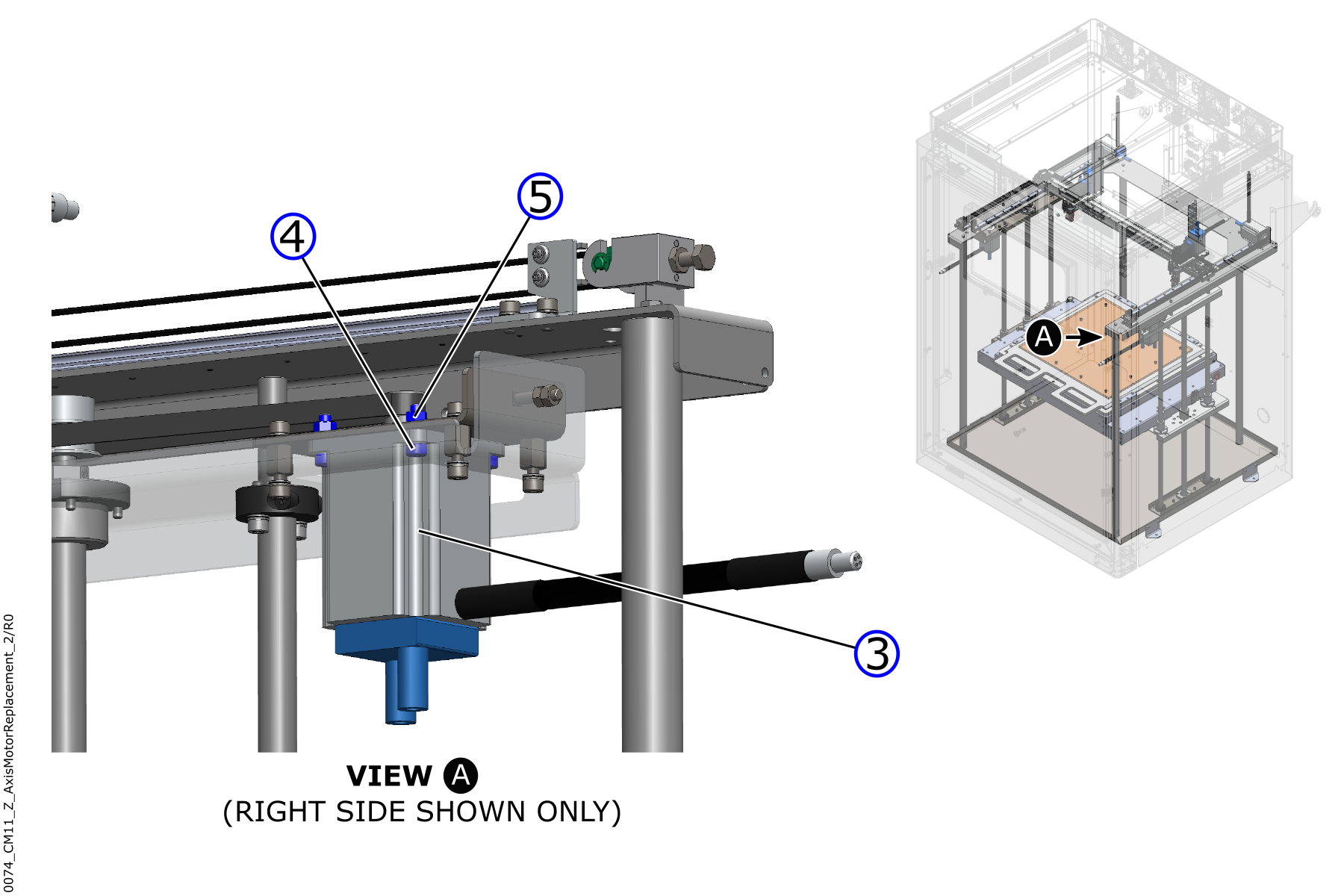
The Z-axis motor (3) will fall when the four screws (4), and the four nuts (5), are removed. Make sure you hold the motor when you remove the last screw (4), and the last nut (5). Failure to do so can cause injuries and/or cause damage to the machine component(s).
Use the digital camera to take a photograph of the orientation of the Z-axis motor (3) on the Z-axis motor bracket, if necessary.
- Use the 4mm hex key and the 8 mm wrench to remove the four screws (4), and the four crush nuts (5), that hold the the Z-axis motor (3) onto the Z-axis motor plate.
- Discard the four crush nuts (5).
- Remove the Z-axis motor (3) from the machine.
- Discard the Z-axis motor (3) in accordance with the local laws and/or regulations.
- Do steps 1 to 8 for the adjacent Z-axis motor, if necessary.
Install the New Z-Axis Motors
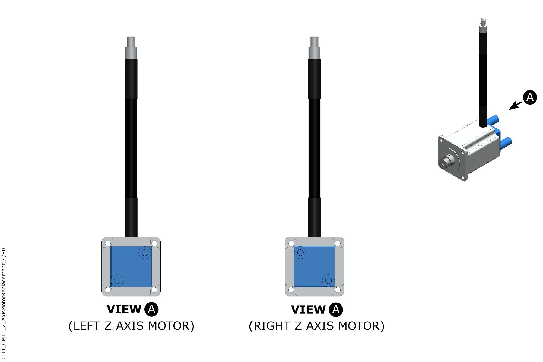
Make sure that the new Z-axis motor (3) configuration is correct (left or right). To correctly identify the Z-axis motor (3) configuration, look at the motor with the water cooling block inlets and outlet ports in front of you (make sure that power cable points up):
• The left Z-axis motor (3) configuration: The water cooling block inlet and outlet ports must point to the right.
• The right Z-axis motor (3) configuration: The water cooling block inlet and outlet ports must point to the left.
Look at the digital photograph(s) of the Z-axis motor (3) orientation to use as a reference to help with the installation procedure.
- Align the four holes in the new Z-axis motor (3) to the four holes in the Z-axis motor plate.
- Make sure that the Z-axis motor (3) power cable points to the build chamber door.
- Use the 4 mm hex key and the 8 mm wrench to install the four screws (4) and four new crush nuts (5). Do not tighten the screws at this point in time.
- Put the bucket in position below the Z-axis motor to collect possible coolant spill.
- Connect the coolant tubes to the new Z-axis motor (3) as follows:
Be careful when the coolant tube clamps are installed. The coolant tubes are soft and the coolant tube clamps can be sharp.
- Use the identification label(s) to install the coolant tubes onto the Z-axis motor (3) cooling block inlet and outlet ports.
- Put the coolant tube clamps in position over the Z-axis motor (3) coolant inlet and outlet ports.
- Use the small flathead screwdriver to tighten the screw of the two coolant tube clamps. Do not tighten too much.
- Connect the new Z-axis motor (3) to the power cable.
- Install the Z-axis belt. Refer to the Replace Z-Axis Belts procedure.
- Adjust the Z-axis belt tension. Refer to Inspect and Adjust XYZ-Axes Belt Tension.
- Fill the cooling system. Refer to the Fill the Cooling Circuit procedure.
- Do steps 1 to 9 for the adjacent Z-axis motor, if necessary.
Test and Return to Service
- Make sure that you remove all the tools from the build chamber.
- Close the build chamber door.
-
- For AON M2+ (CE) machines: Connect power to the machine from the local supply disconnecting device.
- For AON M2+ (R-NZ), AON M2+, AON-M2 2020 and AON-M2 machines: Connect the main power cord to the receptacle.
- Turn the power ON with the ON/OFF switch found on the rear panel of the machine.
- Release the E-stop button.
- Home XYZ.
- Calibrate the Z-axis:
- Refer to Z Offset Calibration (M2+ Klipper) for machines that operates the Klipper-based firmware.
- Refer to Z Offset Calibration (M2+ Marlin) for machines that operates the Marlin-based firmware.
- For the AON-M2 and AON-M2 2020 machines, refer to the Z Offset Calibration procedure.