Replace Z-Axis Microswitches
| Model | [ ] AON M2+ (CE) | [ ] AON M2+ (R-NZ) | [ ] AON M2+ | [•] AON-M2 2020 | [•] AON-M2 |
| Category | [•] Preventive | [•] Corrective | |||
| Frequency | [ ] Daily | [ ] Weekly | [ ] Monthly | [•] Yearly | [ ] As Needed |
For instructions on how to replace the two Z-axis microswitches found on the AON M2+ (CE), AON M2+ (R-NZ) and AON M2+, refer to the Replace Z-Axis Microswitches (M2+) procedure.
Summary
The procedure that follows gives instructions on how to replace the two Z-axis microswitches.
Estimated time: 30 minutes
If the microswitch is replaced as a part of the preventive maintenance plan, the two Z-axis microswitches must be replaced as a pair.
Tools
| Qty | Description | Specification |
|---|---|---|
| 1 | Wrench | 1/4 inch |
| 1 | Hex Key | 5/64 inch |
| 1 | Tape | Non-Glossy |
| 1 | Marker | Fine Tip (preferred) |
| A/R | Rags | Lint-free |
| A/R | Isopropyl Alcohol | 99% |
Parts Information
| Qty | Part Number | Description |
|---|---|---|
| 1 | K-6ED0765E | Z-Axis Microswitch Kit |
| 2 | .F3FC1CC3 | Crouzet Snap Action Microswitch (Included in kit) |
| 8 | . HW-WASH-FLAT-PTFE-#4 | No. 4 Teflon™ Washer (Included in kit) |
| 4 | . HW-WASH-SLEEVE-PTFE-#2 | No. 2 Teflon™ Sleeve Washer (Included in kit) |
| 4 | . HW-CD-NUT-2/56-SS | No. 2 Crush Nut (Included in kit) |
Reach out to our Customer Success team at help@aon3d.com for genuine AON3D replacement part(s).
Personal Protective Equipment
| Qty | Description | Minimum Specification |
|---|---|---|
| 1 | Safety Eyewear | ANSI/ISEA Z87.1 |
| A/R | Nitrile Gloves | ISO 2859-1 or ASTM D6319 |
Prepare the Machine
Make sure that there are no prints on the build surface. Remove print(s) before the procedure that follows is started. Failure to do so can cause a collision and cause damage to the machine component(s).
- Home XYZ.
- Lower the Z-axis by 300 mm.
- Move the Y-axis 450 mm from the home position.
- Push the E-stop button.
- Open the build chamber door.
- Turn the power OFF with the ON/OFF switch found on the rear panel of the machine.
- Disconnect the main power cord from the receptacle.
- Wait until the build chamber, build platform and hot ends are at room temperature.
Remove the Z-Axis Microswitches
Wait until all the machine components are at room temperature before you continue. Some machine components can be hot if the machine was recently used. Failure to do so can cause injuries.
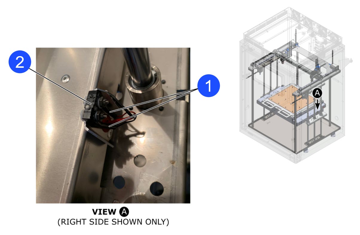
To remove the right Z-axis microswitch (2), do the steps that follow:
- Use the tape and the marker to correctly identify the two wires (1) that connect to the Z-axis microswitch (2).
- Carefully disconnect the two wires (1) from the Z-axis microswitch (2).
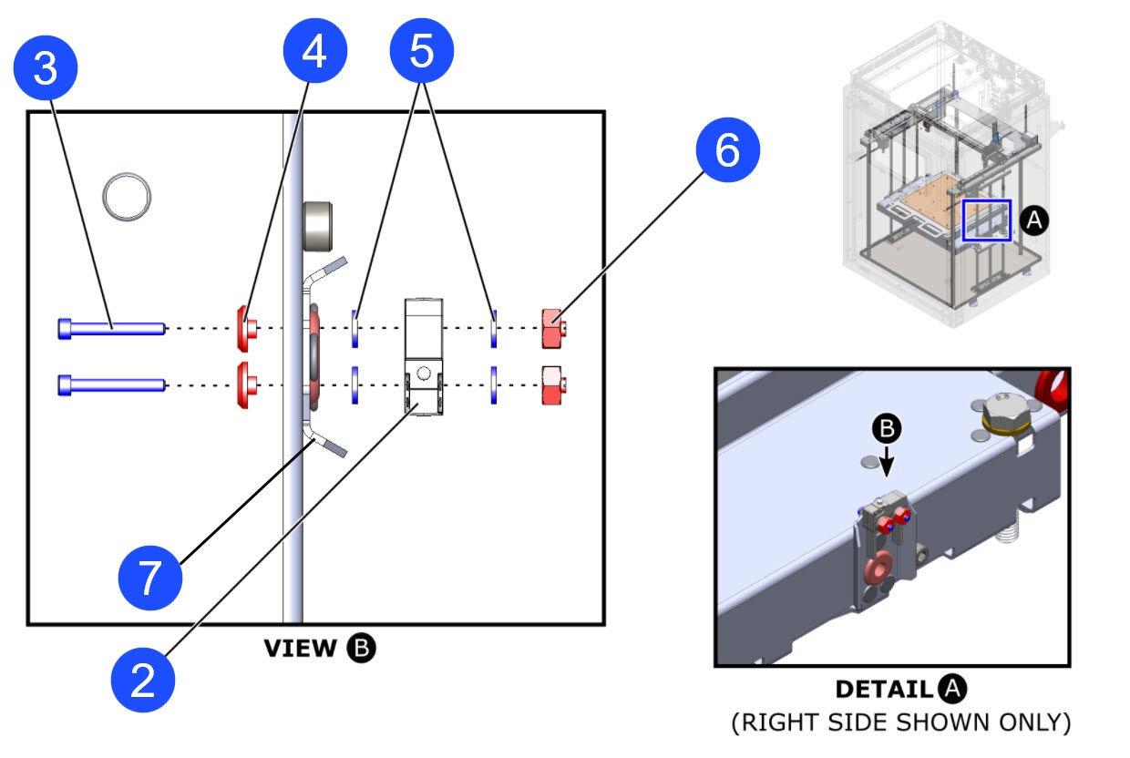
- Use the 5/64 inch hex key and the 1/4 inch wrench to remove the fastener components that follow from the Z-axis microswitch (2):
- two screws (3)
- two Teflon™ sleeve washers (4)
- four Teflon™ washers (5)
- two crush nuts (6).
- Discard the fastener components that follow:
- two Teflon™ sleeve washers (4)
- four Teflon™ washers (5)
- two crush nuts (6).
- Remove the Z-axis microswitch (2) from the Z-axis end stop bracket (7).
- Discard the Z-axis microswitch (2).
- Do steps 2 to 6 with the Z-axis microswitch found on the left side.
Install the New Z-Axis Microswitches
To install the right Z-axis microswitch (2), do the steps that follow:
- Use the isopropyl alcohol and lint-free rag(s) to clean the Z-axis end stop bracket (7).
- Let the Z-axis end stop bracket (7) dry for two minutes.
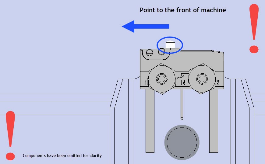
Makes sure to install the Z-axis microswitch in the correct orientation. The microswitch actuator is not in the center of the Z-axis microswitch housing. The microswitch actuator must be offset and point to the front of the machine when installed. Failure to install the Z-axis microswitch correctly can cause damage to machine component(s).
- Put the new Z-axis microswitch (2) in position on the Z-axis end stop bracket (7).
Make sure that there are two Teflon™ washers installed on each side of the Z-axis microswitch. The Z-axis microswitch must not make direct contact with the Z-axis end stop bracket. Failure to install the four Teflon™ washers correctly can cause damage to the Z-axis microswitch, which can cause collisions of machine component(s).
Do not tighten the Z-axis microswitch fastener components too much. Failure to do so can cause damage to the Z-axis microswitch, which can cause collisions of machine component(s).
- Use the the 5/64 inch hex key and the 1/4 inch wrench to install the fastener components that follow:
- two screws (3)
- two new Teflon™ sleeve washers (4)
- four new Teflon™ washers (5)
- two new crush nuts (6).
- Make sure that the Z-axis microswitch (2) is tight on the Z-axis stop bracket (7).
- Use the identification labels to correctly connect the two wires (1) onto the Z-axis microswitch (2) terminals.
- Remove and discard the identification labels.
- Do steps 1 to 7 with the Z-axis microswitch found on the left side.
Test and Return to Service
- Make sure that you remove all the tools from the build chamber.
- Close the build chamber door.
- Connect the main power cord to the receptacle.
- Turn the power ON with the ON/OFF switch found on the rear panel of the machine.
- Release the E-stop button.
- Home XYZ.
- Make sure that the Z-axis microswitches operate correctly. Refer to the Test Microswitches procedure.
- Calibrate the Z-axis. Refer to the Z Offset Calibration procedure.