Victrex AM™ 200 FIL
Victrex AM™ 200 FIL (LMPAEK), is a semi crystalline high performance thermoplastic material. LMPAEK (low-melt polyaryletherketone) offers very high wear resistance, high temperature resistance, fatigue resistance, and corrosion resistance to fluid/chemical. Victrex AM™ 200 Filament is optimized for 3D printing, providing easier printability and improved strength in the z-direction compared to PEEK and PEKK.
Printing Difficulty: Challenging/Expert
AM™ 200 can be purchased from AON3D directly by contacting help@aon3d.com.
- Moisture Control
- Build Platform Adhesion
- General Process Settings
- Post-Processing
- Technical Specifications
- Troubleshooting
Moisture Control
AM™ 200 is extremely susceptible to moisture uptake. Bubbles, popping noises, excessive oozing, and stringing may occur if it has been hydrated.
It is recommended to dry the spool before printing. Install the dry material in the Filament Dry Storage and Feed System to prevent moisture uptake and minimize the impact of moisture on the printing process.
Dry filament at 120ºC for at least 5 hours in a convection oven.
Ensure drying equipment respects our site requirements to ensure adequate drying performance is achieved.
Store filament in air-tight bags or containers alongside silica or zeolite desiccant. Be sure to replace desiccant regularly as its moisture capture ability is exhausted.
Properly dry the material before adjusting process parameters to obtain reliable and consistent results.
For more information, see the Filament Drying and Moisture Control page.
Build Platform Adhesion
For instructions on how to inspect the AON3D build plates, refer to the Inspect and Clean Build Plates procedure.
CF-PEEK Composite Plate
AM™ 200 prints best on the CF-PEEK composite plate.
First Layer Adhesion
To successfully print AM™ 200 on the CF-PEEK composite plate, reduce the First Layer Speed and slightly increase the extrusion temperature for the first layer. Increase the First Layer Height and First Layer Width above 120%.
The first layer adhesion strength may not be enough to prevent warping at warp-prone geometries. If needed, the first few layers of the part may be printed at higher extrusion temperatures, slowly tapering off to overall extrusion temperatures if needed. Start with a First Layer Height and First Layer Width of 100-150% for both and adjust until desired bed adhesion is achieved.
| First Layer Extrusion Temperature | First Layer Speed |
|---|---|
| 390-420ºC | 15-30 mm/s |
For more information, see the Build Platform Adhesion guide.
General Process Settings
For best results, process settings should be adjusted based on model geometry. If you require process development support, our Applications Engineering team can help! Send us a message at help@aon3d.com to consult with one of our Additive Manufacturing Specialists.
| Setting | AON M2+ |
|---|---|
| Extrusion Temperature | 370-440ºC |
| Bed Temperature | 135ºC |
| Chamber Temperature | 90-135ºC |
| Print Speed | 20-45 mm/s |
| Nozzle Size | 0.25-0.60 mm |
| Preferred Build Platform | CF-PEEK Composite Plate |
As with PEEK filaments, it is possible to print AM™ 200 in an amorphous or semi-crystalline state. The crystallization of AM™ 200 is much easier to control than typical PEEK filaments, making it easier to work with. To control warping and deformation during the print, it is generally recommended to use semi-crystalline printing for smaller parts, and amorphous printing for large parts. All parts can be annealed after printing to increase the part performance ; see the Annealing section for instructions.
We recommend two methods of printing AM™ 200:
-
Print with a low-temperature environment: amorphous printing.
The chamber temperature should be set to 90ºC and extrusion temperature to 390ºC. The print will be mostly amorphous with good layer bonding, but annealing will be required afterward. If the part is still showing patches of crystallization, try the methods outlined in the Troubleshooting section. -
Print with a high-temperature environment and high extrusion temperature: semi-crystalline printing.
The chamber should be set to 135ºC and the extrusion temperature to 440ºC. Previous layers will remelt from the nozzle as it moves over it, allowing for some intermixing of the layers before the material crystallizes. If the layers do not mix before crystallizing, they will not stick together. Annealing is not required but recommended to complete crystallization of the material.
Dual Extrusion and Support
To avoid clogging the nozzle, AM™ 200 should not be left idle at printing temperatures. In the provided profiles, the temperature of the hot end is reduced to 300ºC while idle.
For more information, see the Using Supports and Support Materials and Dual Extrusion page.
Infinite Material Solutions AquaSys® 180
Infinite Material Solutions AquaSys® 180 is a compatible soluble support material for AM™ 200.
Note that AquaSys® 180 filament can withstand a maximum chamber temperature temperature of 120ºC before softening in the feed path.
Self-support
AM™ 200 can be printed with self-support. For easy support removal and good support top/bottom contact layer adhesion, use only 1 Upper/Lower Vertical Separation Layer. More than 1 separation layer may risk the supported region of the part to detach and warp.
Sample Slicer Profiles
SuperSlicer
All AON3D-validated materials are available in the SuperSlicer configuration bundle. Refer to SuperSlicer Installation and Update to install and update the SuperSlicer software. Follow the instructions to update to the latest version to ensure you have access to all available materials.
Simplify3D®
Simplify3D® sample profiles for AM™ 200 are available in the Downloadable Assets section.
Post-Processing
Allow all machine components to reach room temperature before proceeding further. Failure to allow components to cool down will result in thermal injury (burns) to personnel.
Shrinkage, deformation, and warpage due to thermal shock may occur from removing the part before letting the machine cool. Instructions for removing the part from the build platform and additional support material can be found on the Build Platform Adhesion and Using Supports and Support Materials guides.
CF-PEEK Composite Plate
AM™ 200 parts separate easily from the CF-PEEK composite plate by hand at room temperature. The use of a spatula can facilitate part removal if needed.
If there are multiple parts on the composite plate, remove the composite plate from the machine before removing the parts. Whereas if the print consists of multiple large/heavy or tall parts, it will be preferable to remove them from the composite plate before removing the sheet from the machine.
Garolite G-10 Build Sheet
AM™ 200 parts separate easily from the Garolite G-10 build sheet by hand at room temperature. The use of a spatula can facilitate part removal if needed.
Annealing
Annealing of AM™ 200 parts must be controlled to achieve a slow crystallization rate by maintaining the lowest temperature that allows crystallization. Therefore, placing the amorphous or semi-crystalline part directly from printing into a high-temperature environment may cause rapid and uneven crystallization, risking extreme warping and deformation. By using a slow and controlled annealing process, crystallization will be slow and even throughout the part. Crystallization-induced shrinkage during the annealing process may be reduced.
Amorphous parts require extra caution when annealing. Since there is more material to crystallize, annealing amorphous parts risks major warping and deformation due to crystallization-induced shrinkage. Semi-crystalline parts do not experience as much crystallization during the annealing process but may still warp and/or deform.
To anneal, place the part in the oven and anneal according to the specifications in the table below. Using the heating rate specified, slowly raise the temperature of the oven to the annealing temperature. Hold the oven at the annealing temperature for the time specified. Allow oven to cool to room temperature before removing the part.
| Annealing Condition | Value |
|---|---|
| Heating rate | 3ºC/min |
| Temperature | 170-180ºC |
| Time | 2-4 hours |
Technical Specifications
Physical Properties
| Property | Value | Test Method |
|---|---|---|
| Linear Density | 31000 g/10000 m | Victrex test method VSH-STM-01 |
| Melting Temperature | 303°C | ISO 11357 |
*All data as reported by Victrex Technical Data Sheet as downloaded on 31/01/2021. Print conditions listed on the Technical Data Sheet.
Troubleshooting
Overheating or crystallization during amorphous printing
If the material is allowed to remain hot for too long, crystallization can occur during amorphous printing. This problem can be seen as a mix of beige-opaque and brownish-translucent extrusions. Overheating can occur during semi-crystalline printing.
To address the effects of these issues without changing your printing approach (ie. without switching between amorphous and semi-crystalline printing), try the following methods:
- Reduce the extrusion temperature by 5-10°C at a time.
- Reduce the print speed.
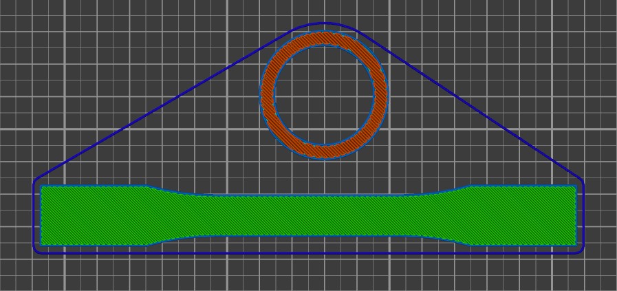
- Add a sacrificial part to increase the layer time.
This allows the material to cool before the new, hot material is added.
The hollow cylinder in the image below is an example of a sacrificial part.
- Print two copies of the same part to increase the layer time.
This allows the material to cool before the new, hot material is added.
Warping on corners or whole part
Sharp corners and large surface areas may have difficulty sticking to the bed. If the First Layer Adhesion methods are not enough to fix the problems, several methods can be used.
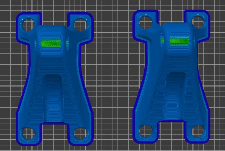
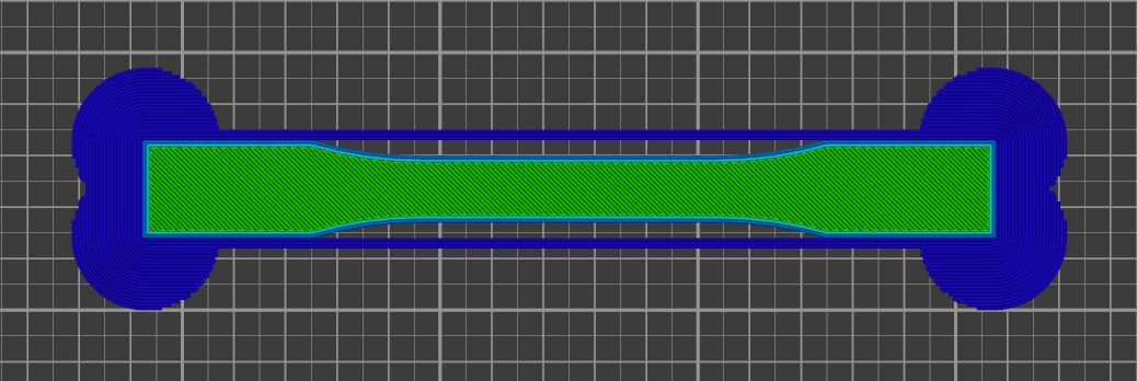
- Brim and brim ears :
Add a very wide brim to the part. In SuperSlicer, add brim ears at the corners, as illustrated below.
- Use the amorphous printing method. Reducing crystallization during the print will reduce shrinkage and thus reduce warping. This method is best for large and/or dense parts.
Stringing
Stringing may become an issue as AM™ 200 tends to stick a lot at its high extrusion temperatures. The nozzle will come into contact with extrusions if the Build Platform has not been properly probed and the Z offset is too small. Material may accumulate on the sides of the nozzle, potentially causing stringing during toolhead movements. Ensure that the bed has been properly probed with a sufficient Z offset distance as shown in the Z Calibration guide.
If stringing/oozing occurs even when Z-axis has been calibrated and the filament has been properly dried and fed from a low humidity environment, increase the Coasting Distance and/or the Wipe Distance before adjusting the Retraction Distance.