Prepare Machine for Shipping
| Model | [•] AON M2+ (CE) | [•] AON M2+ (R-NZ) | [•] AON M2+ | [•] AON-M2 2020 | [•] AON-M2 |
| Category | [ ] Preventive | [•] Corrective |
Summary
The procedure that follows gives the instructions on how prepare the AON3D machine for transport.
Estimated time: 60 minutes
Tools
| Qty | Description | Specification |
|---|---|---|
| 1 | Mallet | Hard Rubber |
| 1 | Phillips Screwdriver | No.2 |
| 2 | Wood Screws | 1 inch length, Phillips No.2 |
| 1 | Hex Key | 4 mm |
Parts Information
| Qty | Description | Specification |
|---|---|---|
| 1 | Crate | Assembly |
| 1 | Insulation Foam | 2 inch width |
| 1 | Velcro® tape | 1 inch width |
Personal Protective Equipment
| Qty | Description | Minimum Specification |
|---|---|---|
| 1 | Safety Eyewear | N/A |
| 1 | Safety Footwear | N/A |
| 1 | Gloves | Work |
Prepare the Machine
- Home XYZ.
- Lower the Z-Axis by 220 mm.
- Push the E-stop button.
- Wait until the build chamber, build platform and hot ends are at room temperature.
Wait until all machine components are at room temperature before you continue. Some machine components can be hot if the machine was recently used. Failure to do so can cause injuries.
- Drain coolant from the machine cooling circuit. Refer to Drain and Replace Coolant.
- After the coolant has been drained, reconnect all coolant lines and/or fittings to their original locations.
- Open build chamber door.
- Turn the power OFF with the ON/OFF switch found on the rear panel of the machine.
- Disconnect and remove the main power AC cord.
If machine is returned under warranty, put the AC power cord at the base of the build chamber.
- Remove the build plate and set aside. Refer to Install Build Plate
Unless otherwise specified by our Customer Success Team, the build plate is not to be returned with the AON3D machine. Reach out to our Customer Success team at help@aon3d.com to confirm.
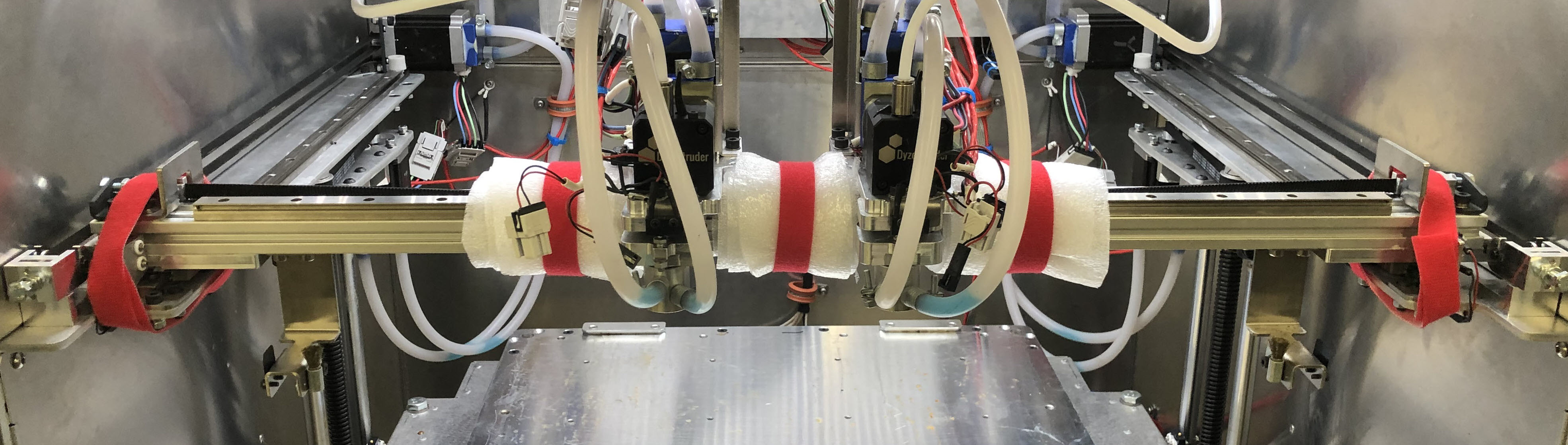
- Manually separate the two toolheads along the X-axis linear rail.
- Wrap foam strip around the radial axis centerline of the X-axis linear rail. Secure foam strip with Velcro® tape.
- Manually position both toolheads against the center foam strip.
- Wrap the two foam strips on both sides of the two toolheads. This will prevent the movement of the two toolheads.
- Secure the two foam strips with Velcro® tape.
- Make sure toolheads are tight on the X-axis linear rail.
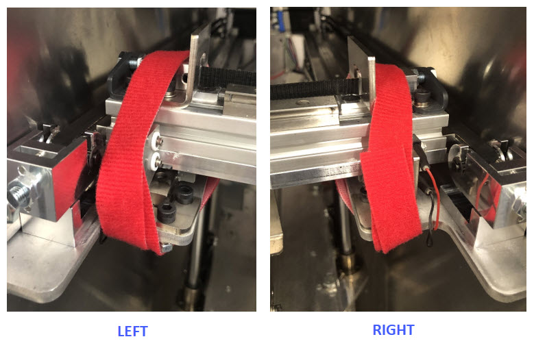
- Secure both the X-gantry ends to the Y-axis rails with Velcro® tape.
- Make sure the X-gantry is secure at both ends.
- Close and lock the build chamber door.
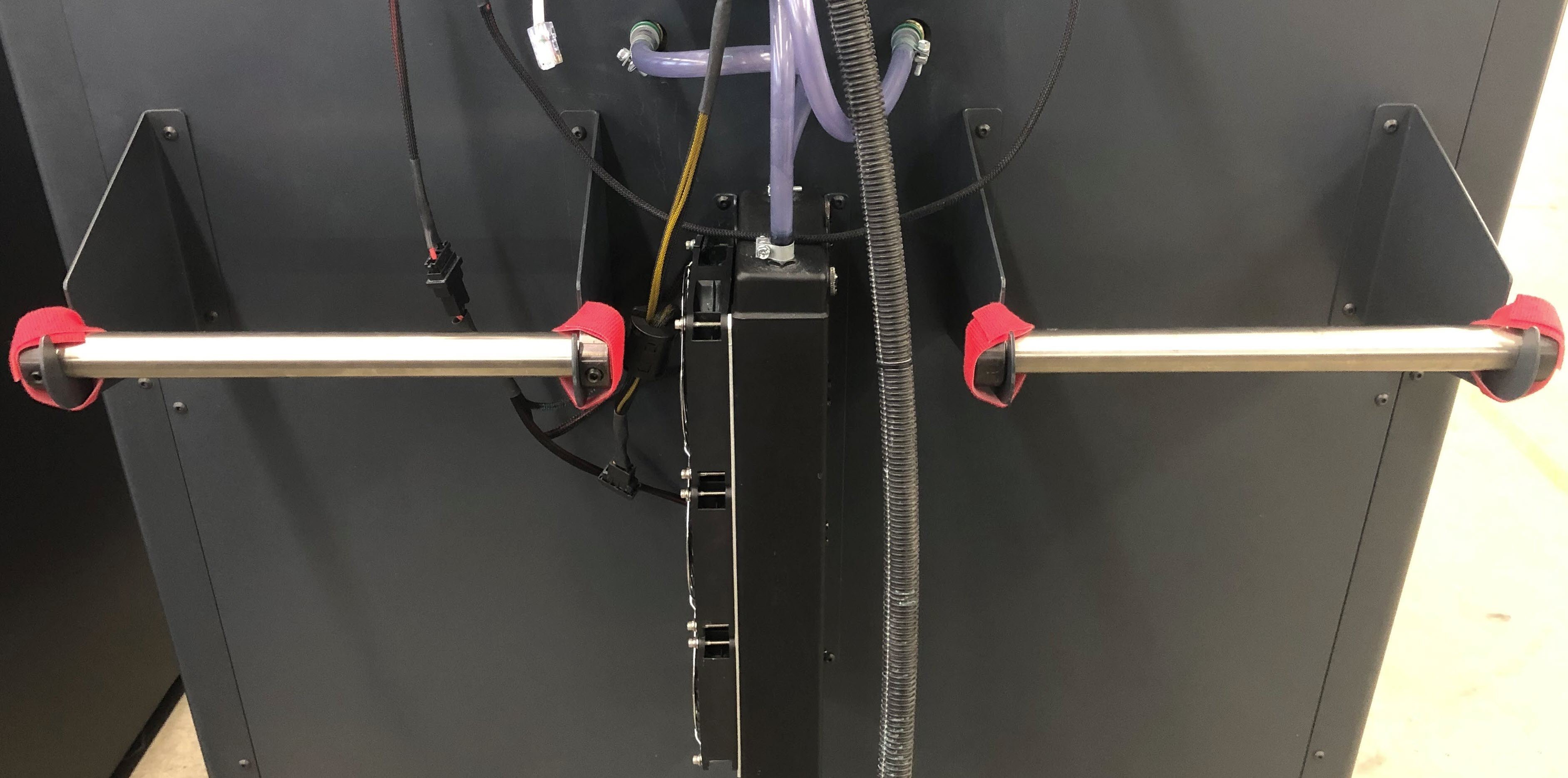
- Use the Velcro® tape to secure the two filament spool holders to the two spool holder brackets.
Put the Vacuum Pump on the Machine
The vacuum pump is mounted to the machine for ease of movement and shipping. It must be put on the machine before shipping.
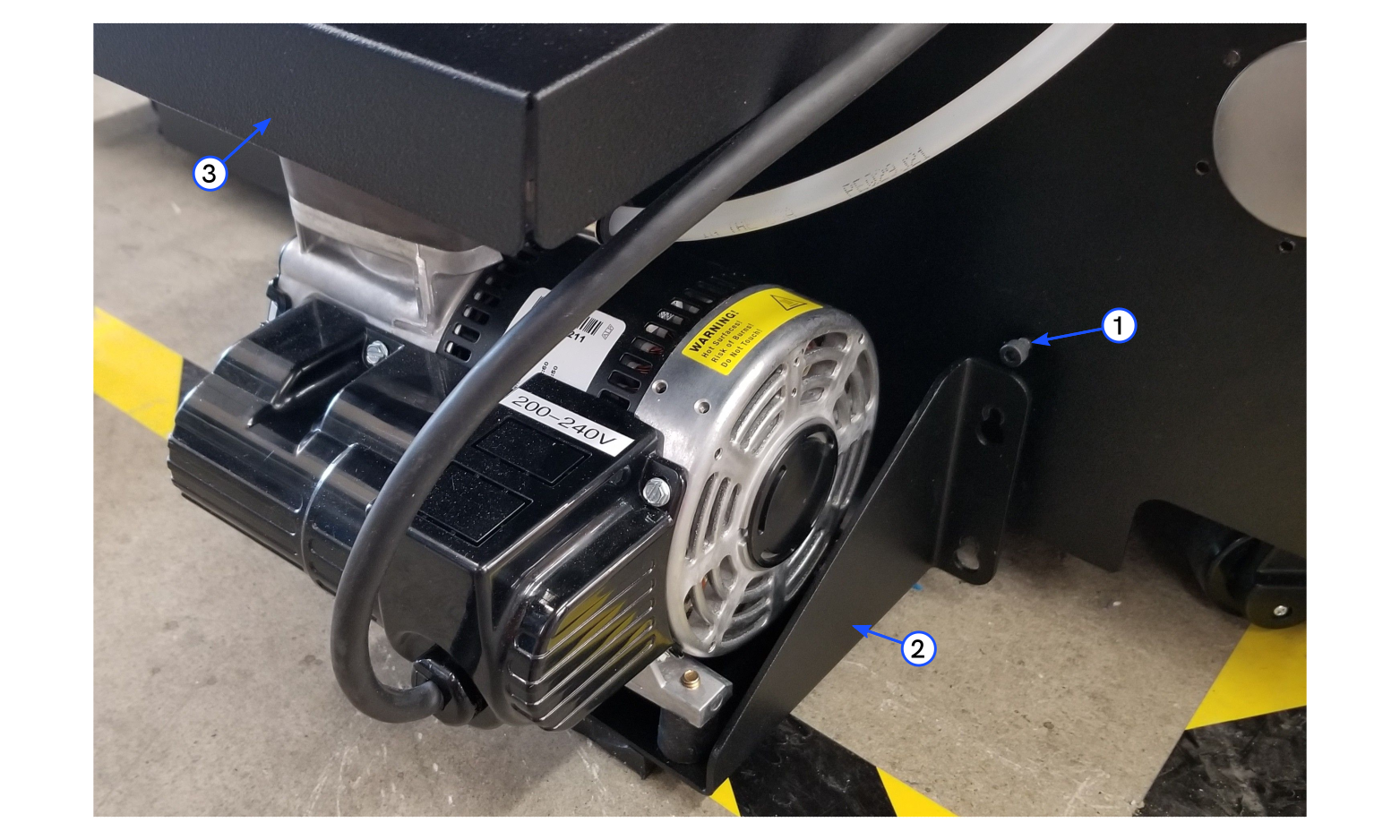
- Lift the vacuum pump assembly (2) from the floor and put it on the machine.
- Use the 4 mm hex key to tighten the four screws (1).
Prepare Shipping Crate
Prepare Platform & Front Panel Assembly
- Place the crate platform onto the floor.
- Put the front crate panel into position on the crate platform.
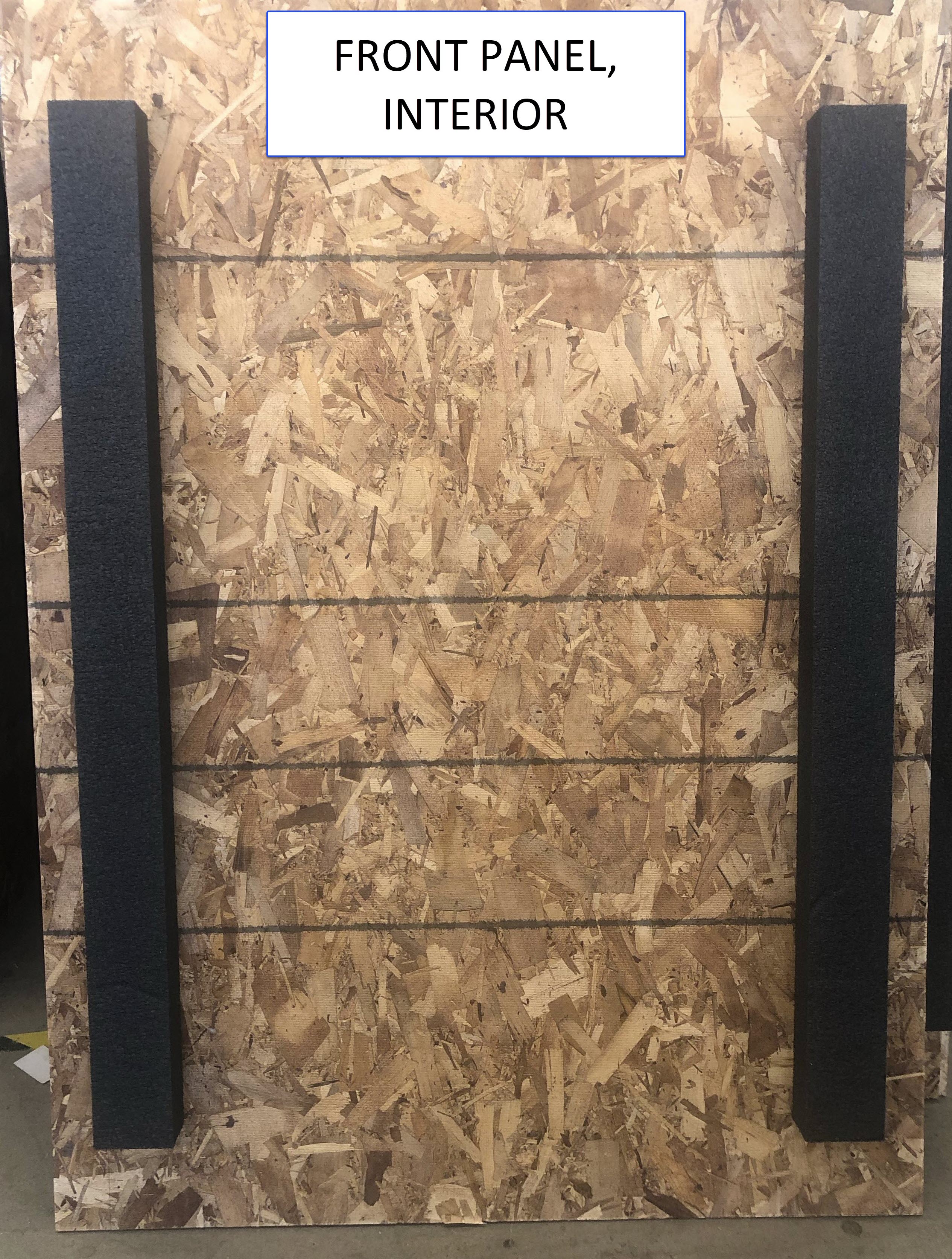
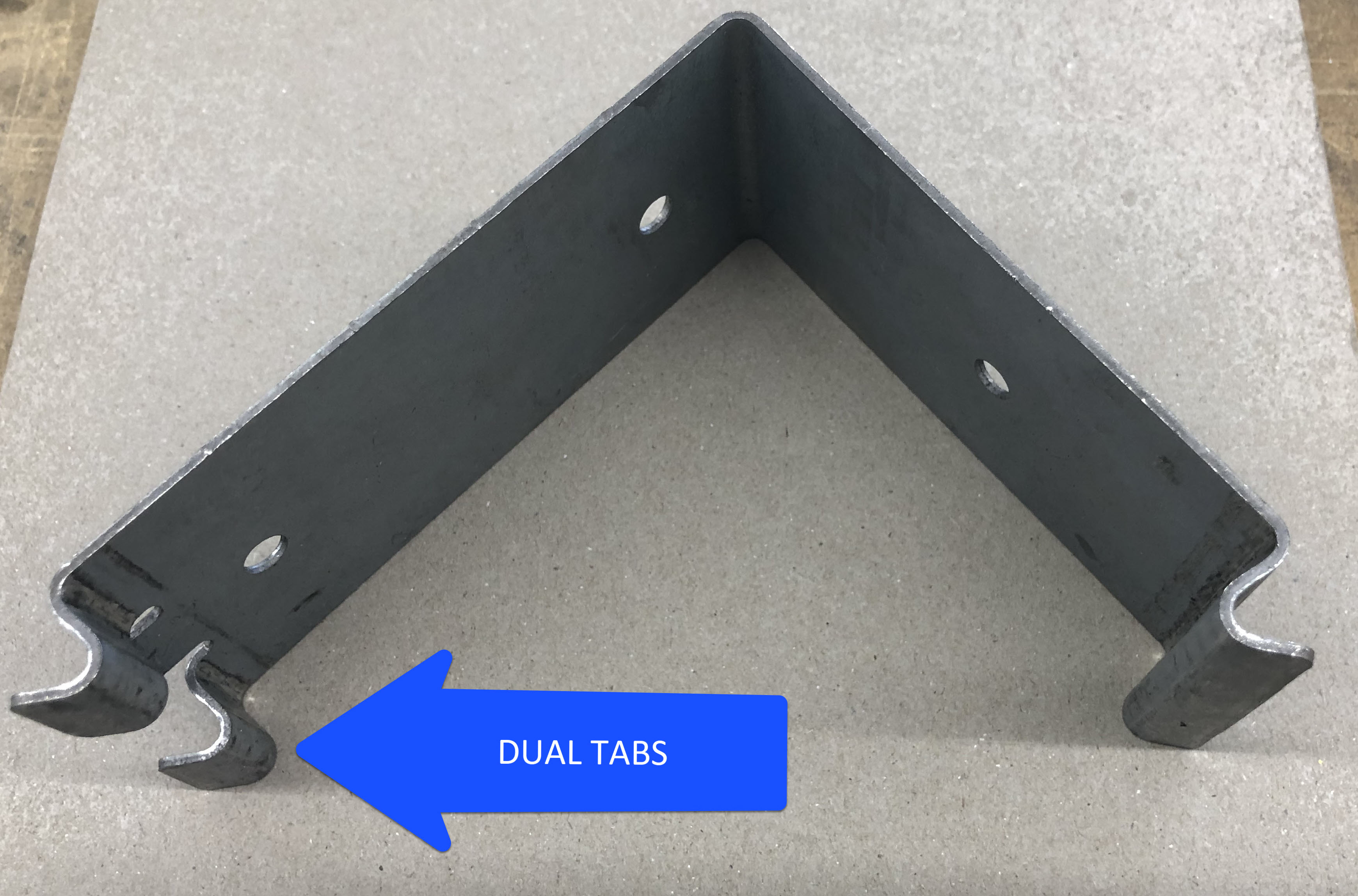
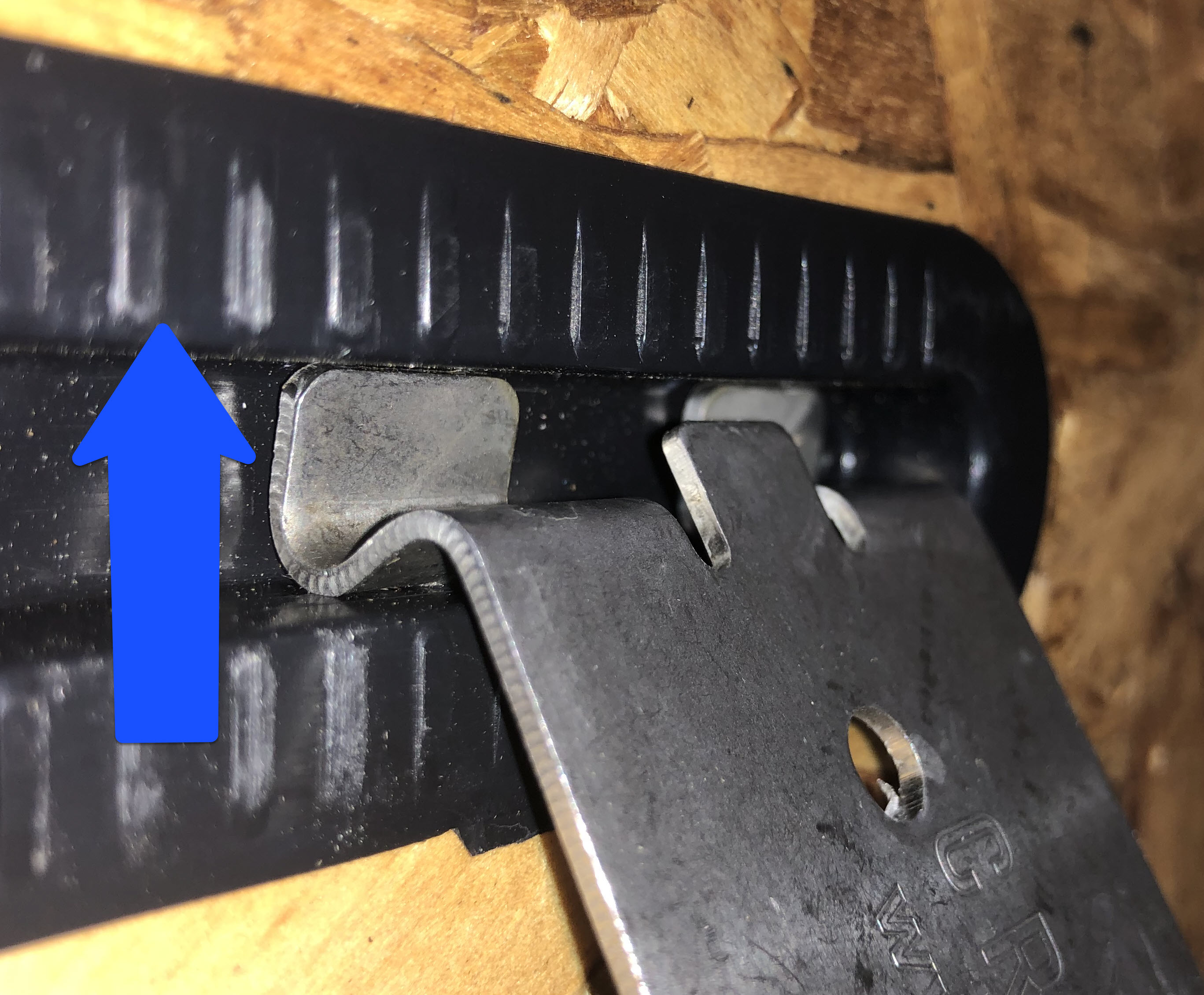
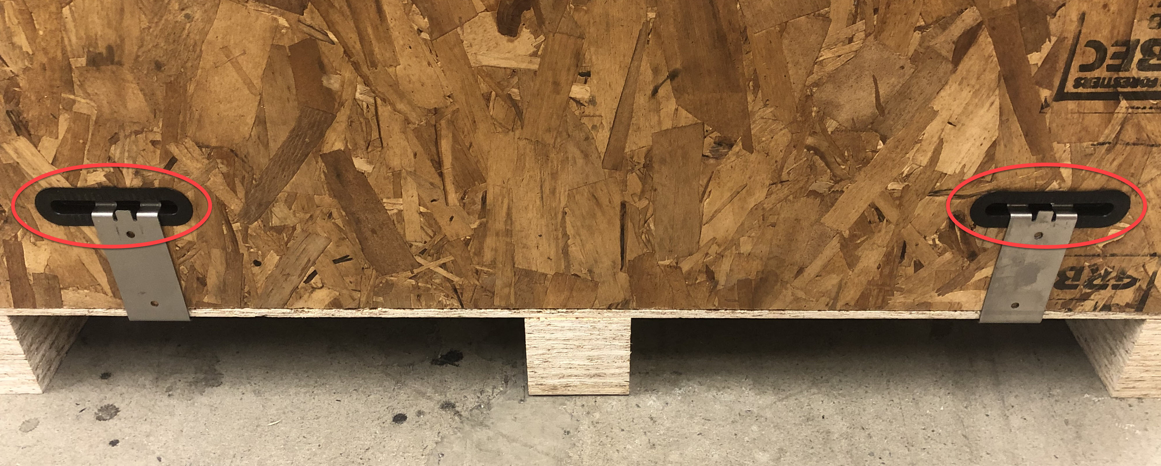
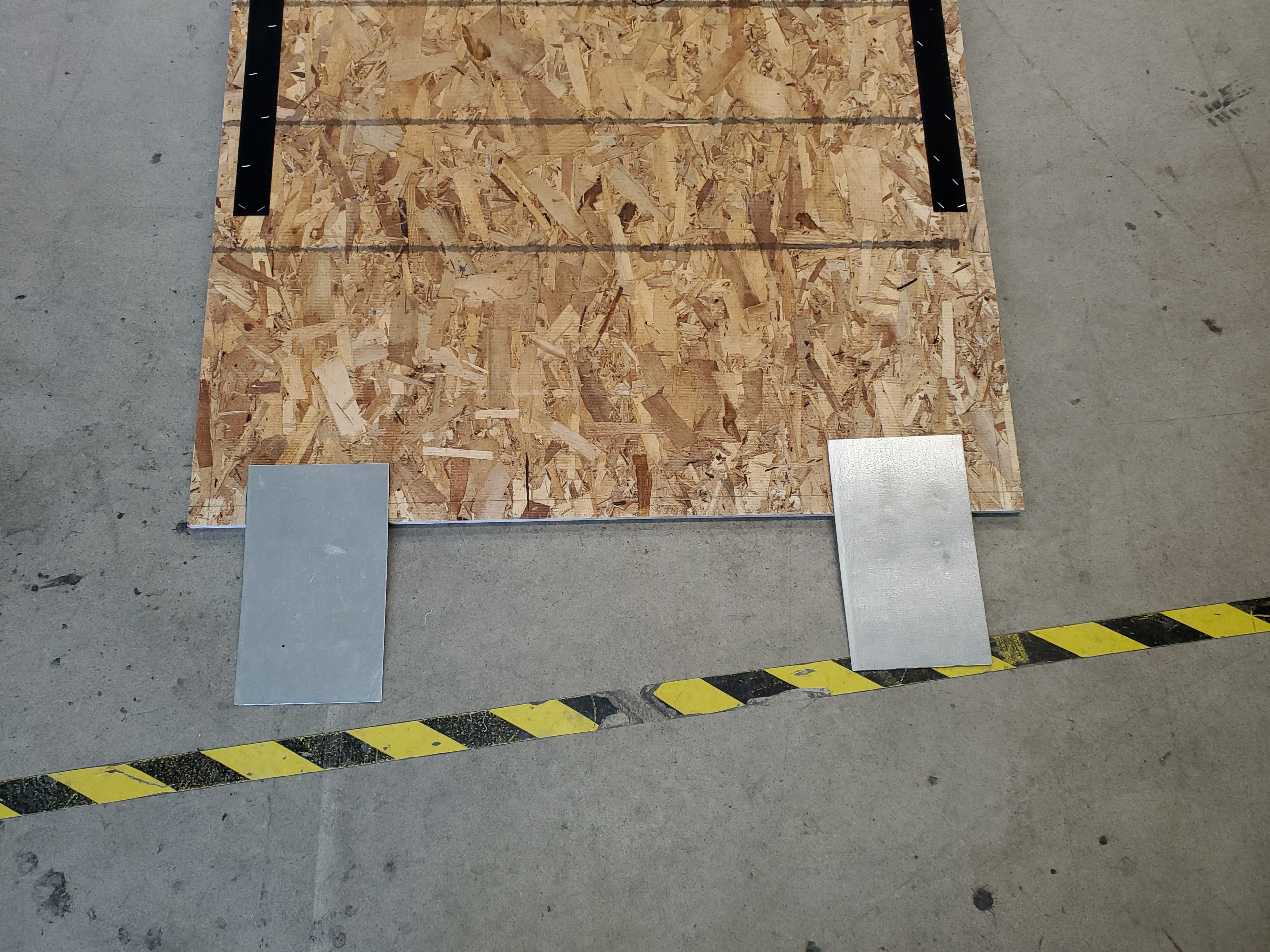
- Install two metal clips where the front panel meets the crate platform.
Use a hard rubber mallet to help install the metal clips.
Make sure that the two tabs on the metal clips point up when the front panel is installed on the crate platform.
Prepare and Install the Ramp Assembly
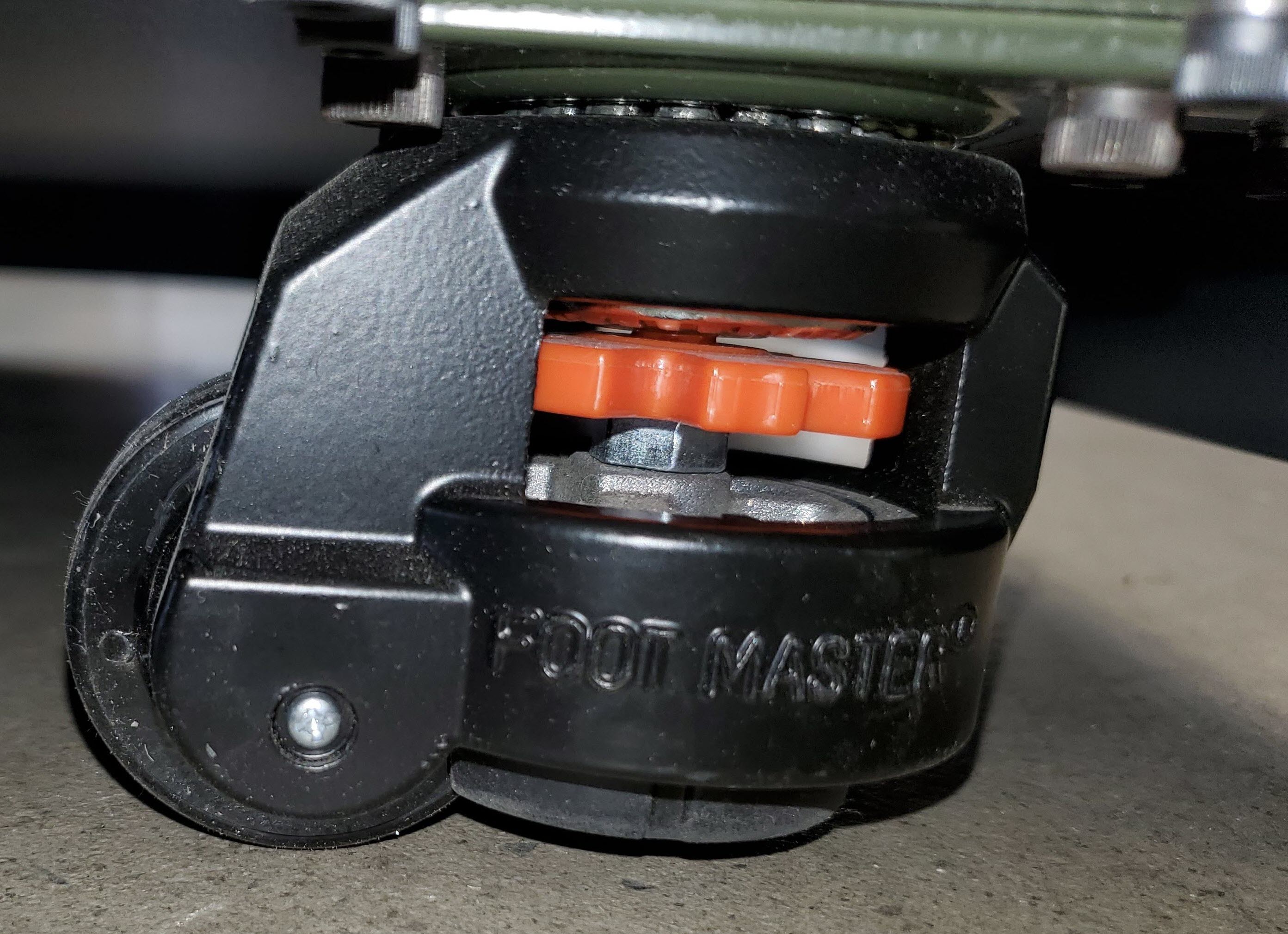
- Unlock the four caster wheels by rotating each of their orange leveling nuts, ensuring machine will roll smoothly onto the ramp.
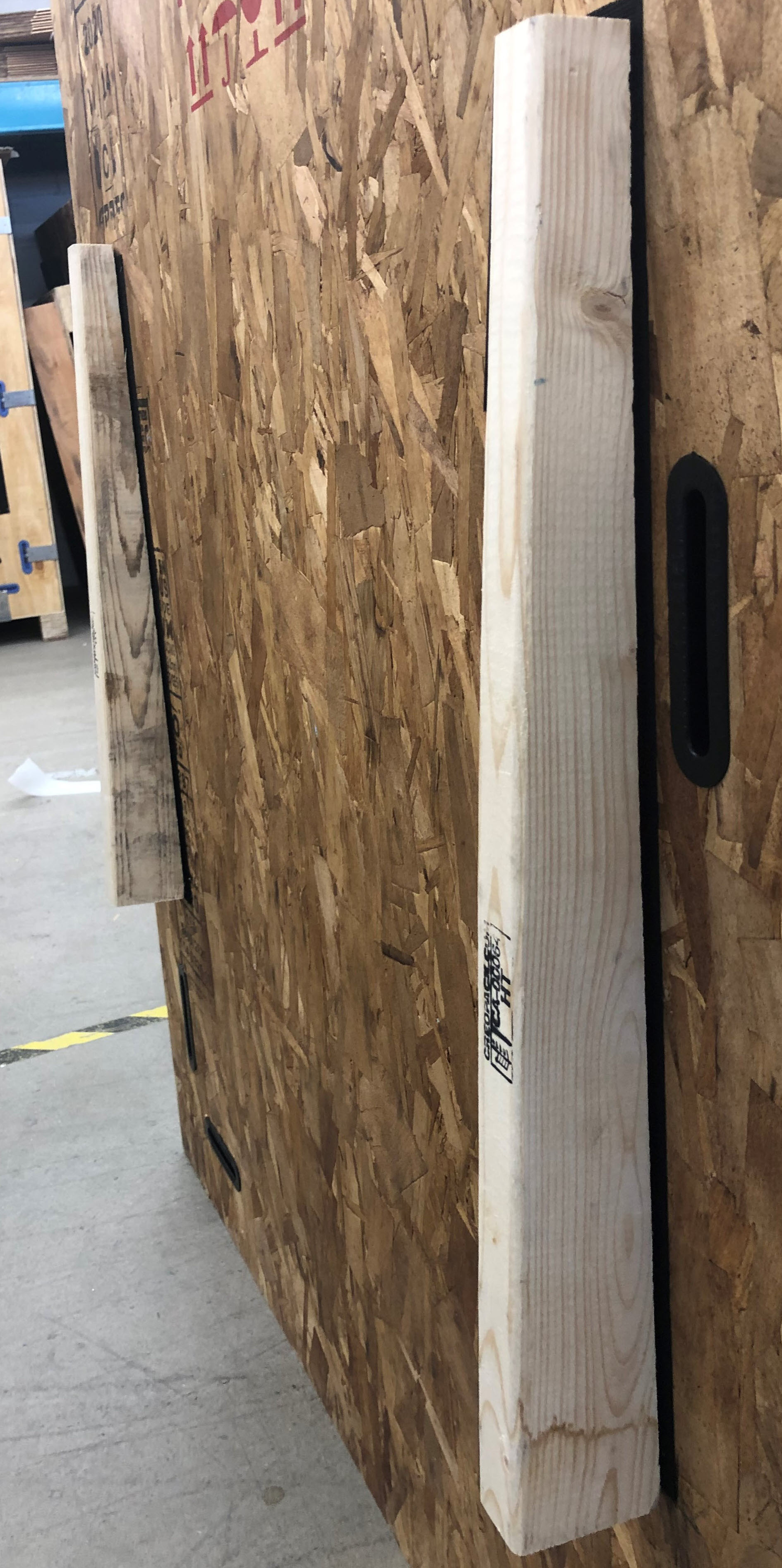
- Locate the two wooden triangular-shaped support blocks and metal ramp strips on the inside of the rear panel.
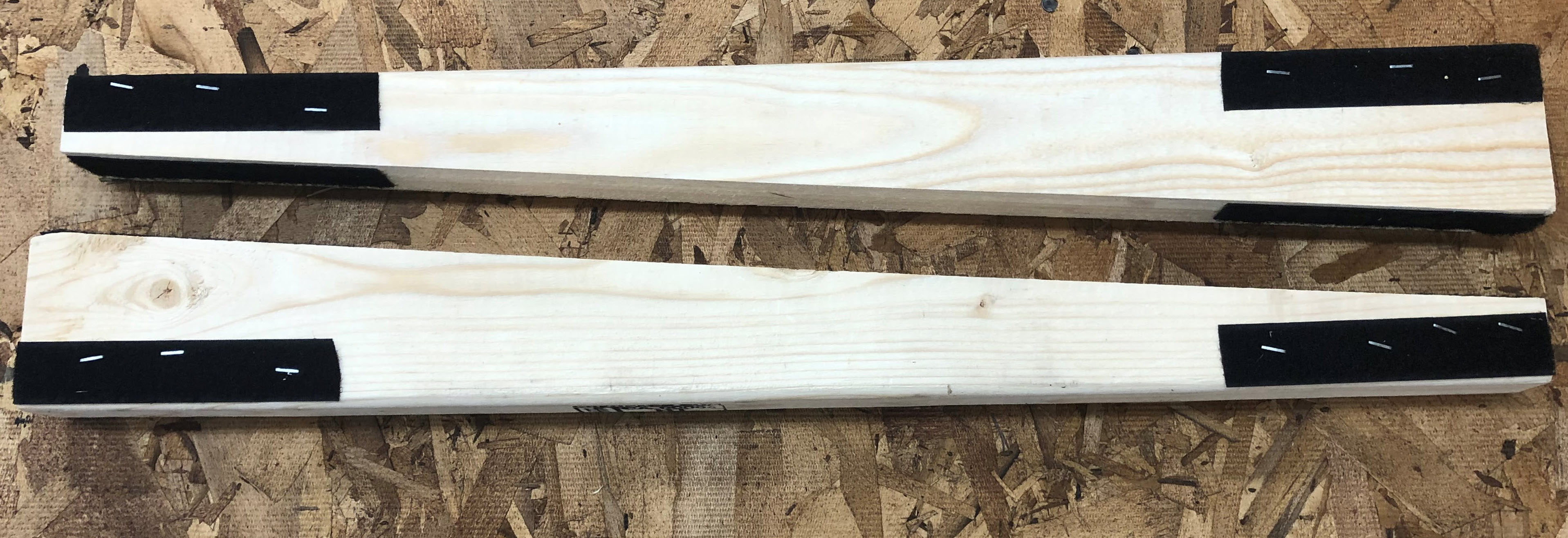
- Assemble the ramp by placing the two wooden triangular-shaped support blocks under the ramp using the preattached Velcro® strips.
- Position the ramp on the floor and ensure the gap between the crate platform and the ramp is minimal.
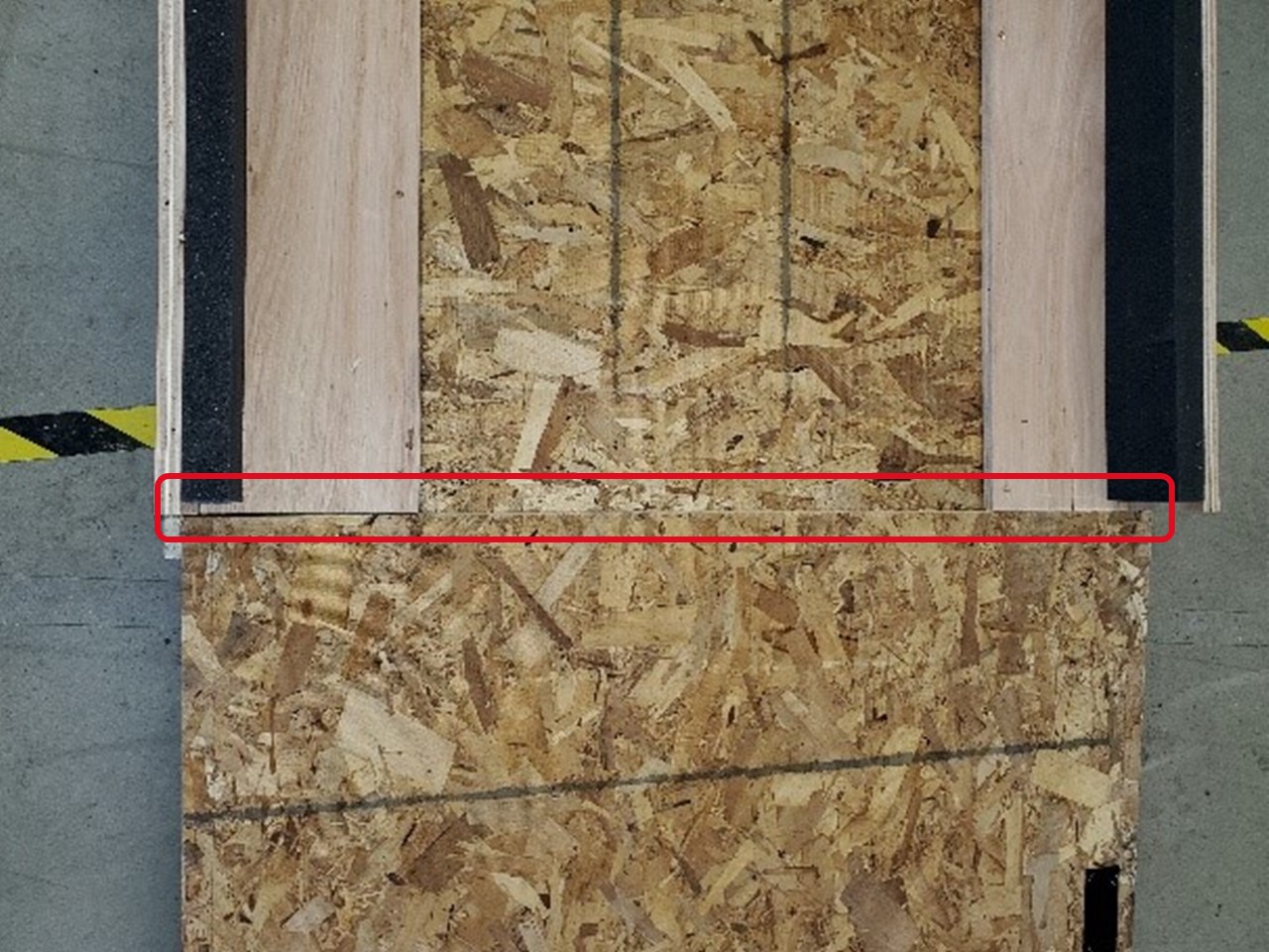
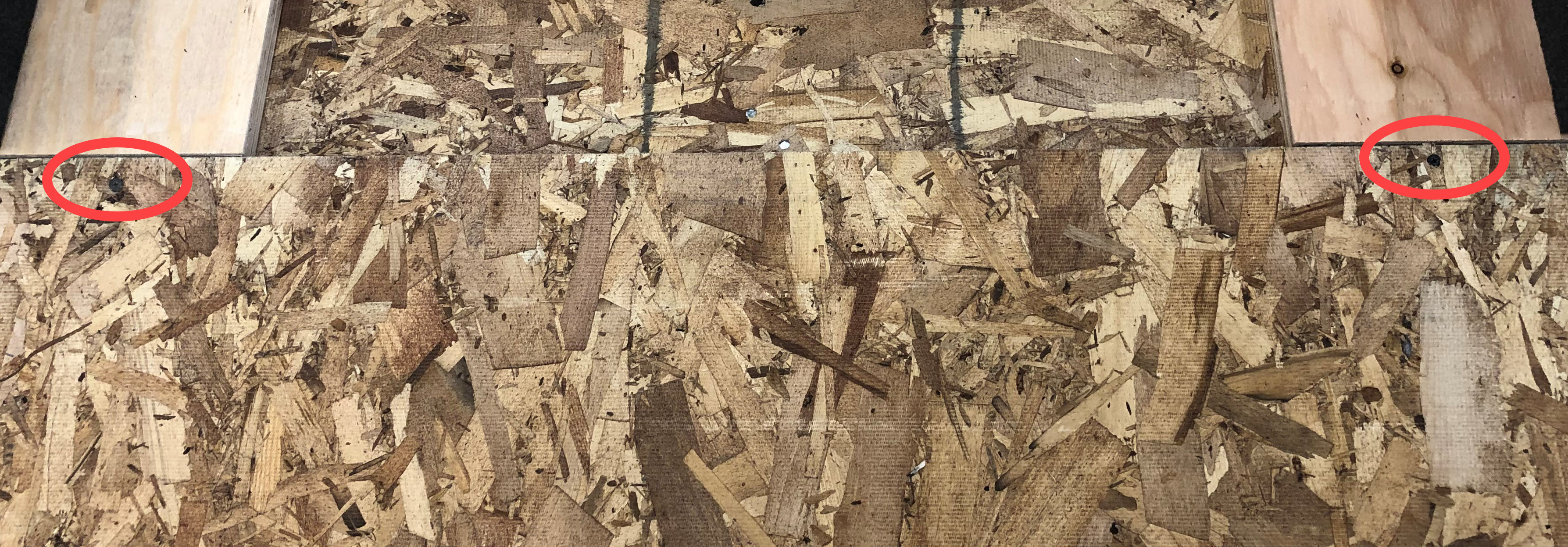
- Using two wood screws, secure ramp onto the crate platform as shown below.
- Position the two metal ramp strips onto the ramp using the preattached Velcro® strips.
Load the AON3D Machine Onto Crate Platform
Prior to loading the machine onto the crate platform, verify that all the following tasks have been completed:
• Coolant has been drained.
• All coolant lines/fittings haven been installed to their original locations.
• Z-Axis lowered by 300 mm.
• Build plate has been removed.
• Both toolheads are secured to the X-gantry rail.
• X-gantry rail secured to the Y-axis rails at both ends.
• Push the E-stop button.
• Main power switch engaged to OFF position at rear of machine.
• Filament spool holders are secured to their respective brackets.
• Build chamber door closed and latch is firmly engaged.
• Four caster wheels are unlocked.
The front of the machine must be loaded onto the platform first.
Always use a minimum of two individuals for the procedure that follows. The machine weighs over 330 kg (720 lbs.) and can cause injury to personnel or damage equipment if control is lost during movement.
- Carefully push the machine onto the crate platform.
- Position the front panel of the machine against foam on the inside of front crate panel.
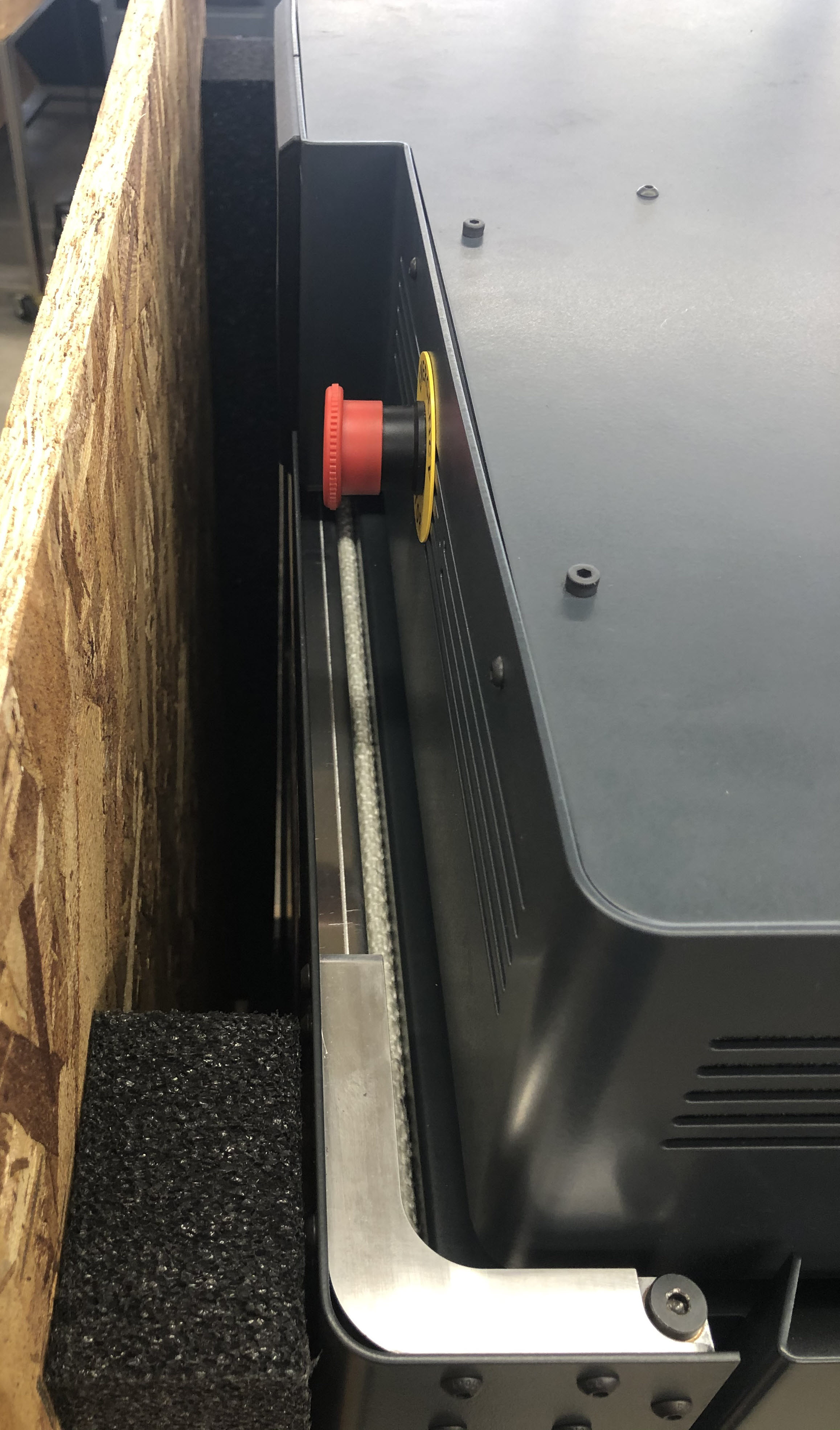
- Once the machine is positioned, lock the two rear caster wheels by rotating each of their orange leveling nuts.
Install the Right and Left Side Panels
The right and left side panels are installed as illustrated below.
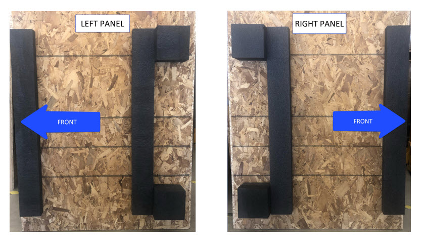
- Position the right and the left side panels onto platform against the front panel.
- Secure both the right and left side panels to the front panel with six metal clips: three metal clips per side.
- Secure both the right and left panels onto the platform using four metal clips: two metal clips per side.
Make sure to install the metal clips with the two metals tabs facing upwards when securing right and left panels onto the platform.
Remove and Disassemble the Ramp
- Remove the two wood screws which secure ramp to the crate platform.
- Remove the two sheet metal ramp strips.
- Remove the ramp and set aside as to have access to the two wooden triangular-shaped support blocks.
- Remove two wooden triangular-shaped support blocks.
- Attach two metal ramp strips and two wooden triangular-shaped support blocks to the inside of the (now) rear panel.
Install the Rear Panel
- Install rear panel onto the crate platform.
- Make sure the rear panel mates properly to the right and left side panels.
- Secure the rear panel to right and left side panels with six metal clips: three metal clips per side.
- Secure the rear panel onto the crate platform using two metal clips.
Make sure to install the metal clips with two metals tabs facing upwards when securing rear panel onto crate platform.
Install the Top Cover
- Lower top cover onto the crate enclosure.
- Make sure the top cover mates properly with the right, left, front and rear panels.
- Secure top cover to the four panels using eight metal clips: two metal clips per side.
Final Inspection and Steps
- Make sure all 28 metal clips are installed and firmly snapped into position.
- Secure transparent shipping envelope on the rear panel.
- Insert shipping label into shipping envelope. Seal envelope closed.