Replace Heater Block Assemblies
| Model | [•] AON M2+ (CE) | [•] AON M2+ (R-NZ) | [•] AON M2+ | [•] AON-M2 2020 | [•] AON-M2 |
| Category | [ ] Preventive | [•] Corrective |
Summary
The procedure that follows gives the instructions on how to replace the two heater block assemblies.
Estimated time: 15 minutes
Tools
None required.
Parts Information
| Qty | Part Number | Description |
|---|---|---|
| 2 | M2-SUB-HOT-END-HTR-BLK-0.2-R01 | M2 Hot End HTR BLK Sub-Assy - 0.2 mm |
| 2 | M2-SUB-HOT-END-HTR-BLK-0.25-R01 | M2 Hot End HTR BLK Sub-Assy - 0.25 mm |
| 2 | M2-SUB-HOT-END-HTR-BLK-0.3-R01 | M2 Hot End HTR BLK Sub-Assy - 0.3 mm |
| 2 | M2-SUB-HOT-END-HTR-BLK-0.4-R01 | M2 Hot End HTR BLK Sub-Assy - 0.4 mm |
| 2 | M2-SUB-HOT-END-HTR-BLK-0.8-R01 | M2 Hot End HTR BLK Sub-Assy - 0.8 mm |
| 2 | M2-SUB-HOT-END-HTR-BLK-1.0-R01 | M2 Hot End HTR BLK Sub-Assy - 1.0 mm |
| 2 | M2-SUB-HOT-END-HTR-BLK-1.2-R01 | M2 Hot End HTR BLK Sub-Assy - 1.2 mm |
| 2 | A-000268 | M2 Hot End HTR BLK Sub-Assy - Tungsten Carbide Nozzle - 0.4 mm |
| 2 | A-000269 | M2 Hot End HTR BLK Sub-Assy - Tungsten Carbide Nozzle - 0.6 mm |
Reach out to our Customer Success team at help@aon3d.com for genuine AON3D replacement part(s).
Personal Protective Equipment
| Qty | Description | Minimum Specification |
|---|---|---|
| 1 | Safety Eyewear | ANSI/ISEA Z87.1 |
| A/R | Gloves | Work |
Prepare the Machine
- Unload the filament. Refer to Replace Filament.
- Home XYZ.
- Lower the Z-axis by 300 mm.
- Open the build chamber door.
- Push the E-stop button.
- Turn the power OFF with the ON/OFF switch found on the rear panel of the machine.
-
- For AON M2+ (CE) machines: Disconnect power to the machine from the local supply disconnecting device.
- For AON M2+ (R-NZ), AON M2+, AON-M2 2020 and AON-M2 machines:
Disconnect the main power cord from the receptacle.
Dangerous voltages continue to be found in the electrical panel when the ON/OFF switch is set to OFF. Disconnect the main power cord from the machine while maintenance is done. Failure to do so can cause electric shock.
- Wait until the build chamber, build platform and hot ends are at room temperature.
Remove the Heater Block Assembly
Wait until all machine components are at room temperature before you continue. Some machine components can be hot if the machine was recently used. Failure to do so can cause injuries.
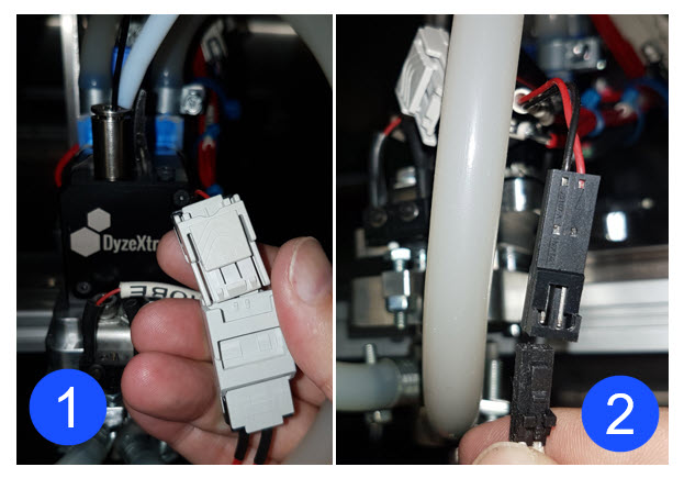
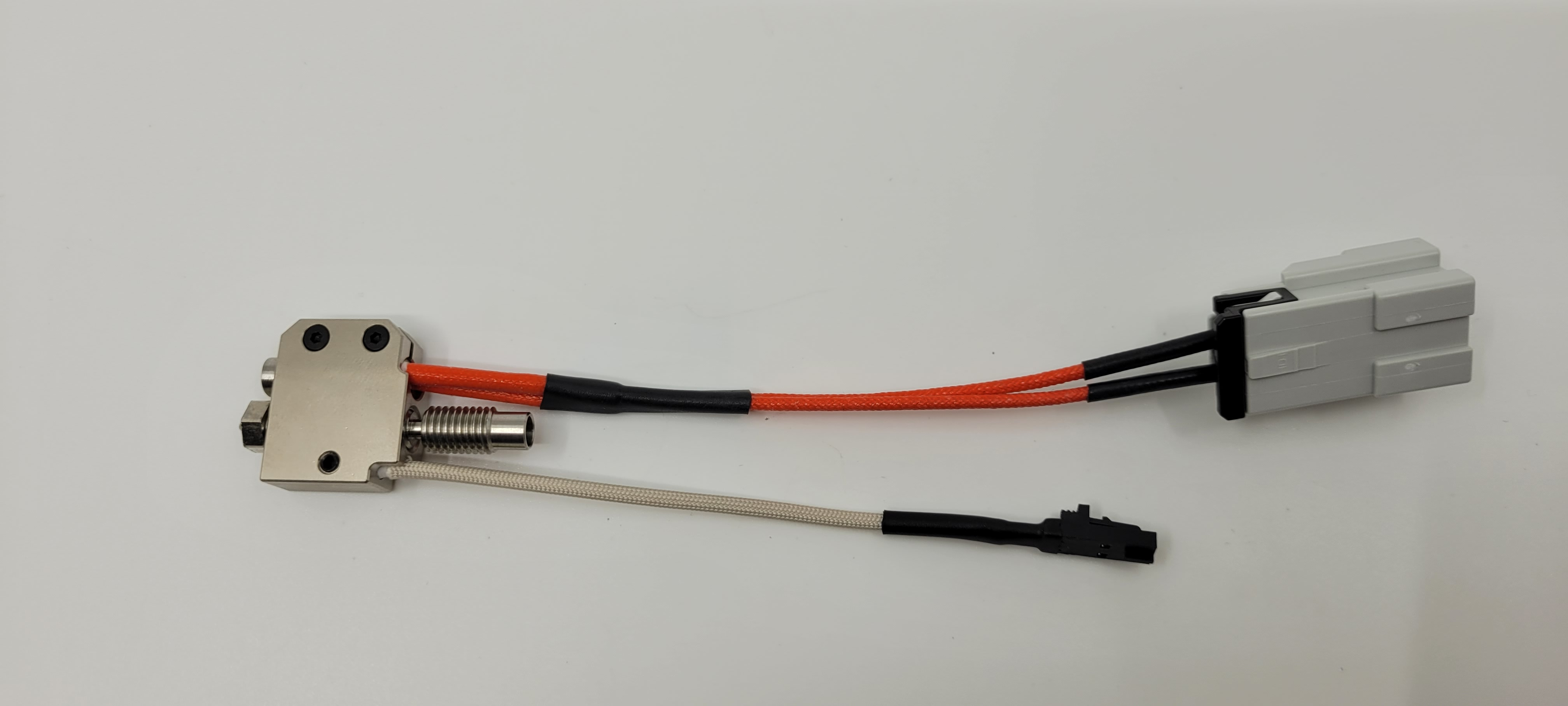
- Disconnect the components that follow:
- Heater cartridge (1)
- RTD sensor plug (2).
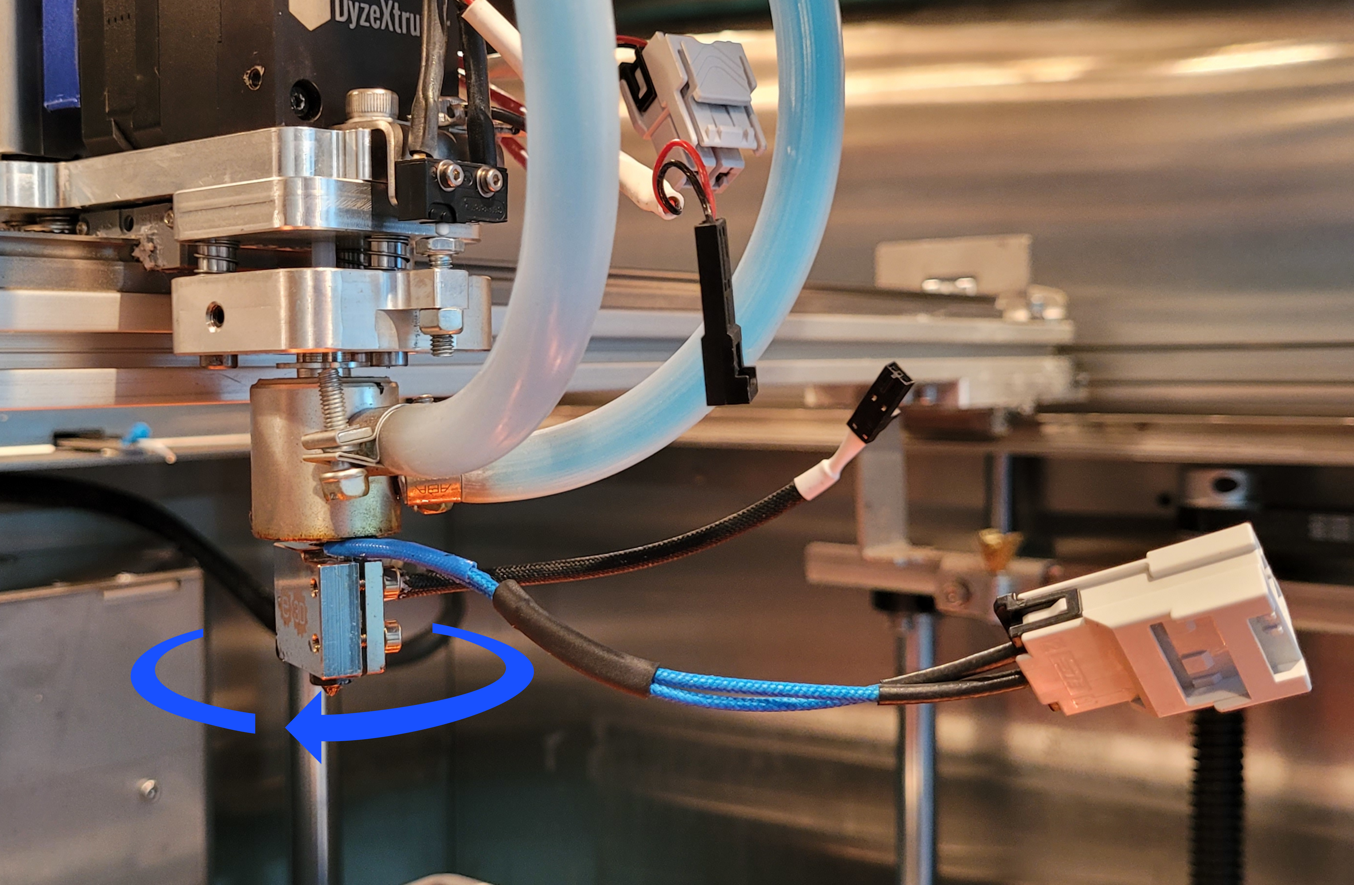
- Carefully rotate the heater block assembly clockwise to remove it from the water cooled heat sink.
There is a small PTFE tube that is installed in between the bottom of the extruder through the heat sink into the top of the heat break. This is a crucial piece of the filament feed path. The small PTFE tube can stick in the heat break and come out when removed from the heater block assembly. Be careful not to lose it, and make sure to replace it when you install the new assembly.
- Carefully remove the small PTFE tube from the heat break.
- Do steps 1 to 3 for the adjacent toolhead, if necessary.
Do not bend the heat break when the heater block assembly is removed. Failure to do so can cause damage to the heat break.
Install the Heater Block Assembly
Do not apply any lubricants to the heat break threads. The heat break must be installed dry.
Do not bend the heat break when the heater block assembly is installed. Failure to do so can cause damage to the heat break.
Do not use the Vise-Grip™ to install and/or tighten the heater block assembly. The use of Vise-Grips™ can cause damage to machine component(s).
- Carefully install the small PTFE tube into the heat break.
- Carefully rotate the heater block assembly counterclockwise to install it to the water cooled heat sink.

- Tighten the heater block assembly by hand. Do not tighten too much.
- Connect the components that follow:
- Heater cartridge
- RTD sensor.
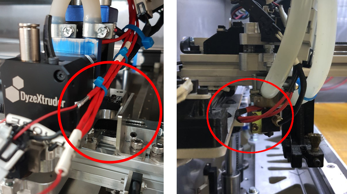
- Make sure the heater cartridge and the PT100 RTD sensor wires are correctly attached and do not get caught in the machine component(s) when the toolhead is in the home position. Make sure that the areas circled in red do not have caught wires.
- Do steps 1 to 5 for the adjacent toolhead, if necessary.
Test and Return to Service
- Make sure that you remove all the tools from the build chamber.
- Close the build chamber door.
-
- For AON M2+ (CE) machines: Connect power to the machine from the local supply disconnecting device.
- For AON M2+ (R-NZ), AON M2+, AON-M2 2020 and AON-M2 machines: Connect the main power cord to the receptacle.
- Turn the power ON with the ON/OFF switch found on the rear panel of the machine.
- Release the E-stop button.
- Home XYZ.
- Test the RTD sensor(s). Refer to Inspect and Test RTD Sensors.
- Load the filament. Refer to Replace Filament.