Replace X-Axis Belt
| Model | [•] AON M2+ (CE) | [•] AON M2+ (R-NZ) | [•] AON M2+ | [•] AON-M2 2020 | [•] AON-M2 |
| Category | [ ] Preventive | [•] Corrective |
Summary
The procedure that follows gives the instructions on how to replace the X-axis belt.
Estimated time: 45 minutes
Tools
| Qty | Description | Specification |
|---|---|---|
| 1 | Hex Key | 2 mm |
| 1 | Hex Key | 4 mm |
| 1 | Wrench | 10 mm |
| 1 | Torque Wrench | 0-10 N·m range, calibrated |
| 1 | Hex Bit | 4 mm |
| 1 | Socket | 4 mm, 1/4 inch drive |
| 1 | Ruler or Tape Measure | N/A |
Parts Information
| Qty | Part Number | Description |
|---|---|---|
| 1 | ME-BELT-GT2-9-HT-OPEN-885 | Open GT2 Timing Belt, High Temp, 885mm |
| 4 | HW-SS-TOOTH-WASH-M5 | 18-8 Stainless Steel Internal-Tooth Lock Washer |
Reach out to our Customer Success team at help@aon3d.com for genuine AON3D replacement part(s).
Personal Protective Equipment
| Qty | Description | Minimum Specification |
|---|---|---|
| 1 | Safety Eyewear | ANSI/ISEA Z87.1 |
| A/R | Nitrile Gloves | ISO 2859-1 or ASTM D6319 |
Prepare the Machine
- Home XYZ.
- Lower the Z-axis by 300 mm.
- Open the build chamber door.
- Push the E-stop button.
- Turn the power OFF with the ON/OFF switch found on the rear panel of the machine.
-
- For AON M2+ (CE) machines: Disconnect power to the machine from the local supply disconnecting device.
- For AON M2+ (R-NZ), AON M2+, AON-M2 2020 and AON-M2 machines:
Disconnect the main power cord from the receptacle.
Dangerous voltages continue to be found in the electrical panel when the ON/OFF switch is set to OFF. Disconnect the main power cord from the machine while maintenance is done. Failure to do so can cause electric shock.
- Wait until the build chamber, build platform and hot ends are at room temperature.
Remove the X-Axis Belt
Wait until all the machine components are at room temperature before you continue. Some machine components can be hot if the machine was recently used. Failure to do so can cause injuries.
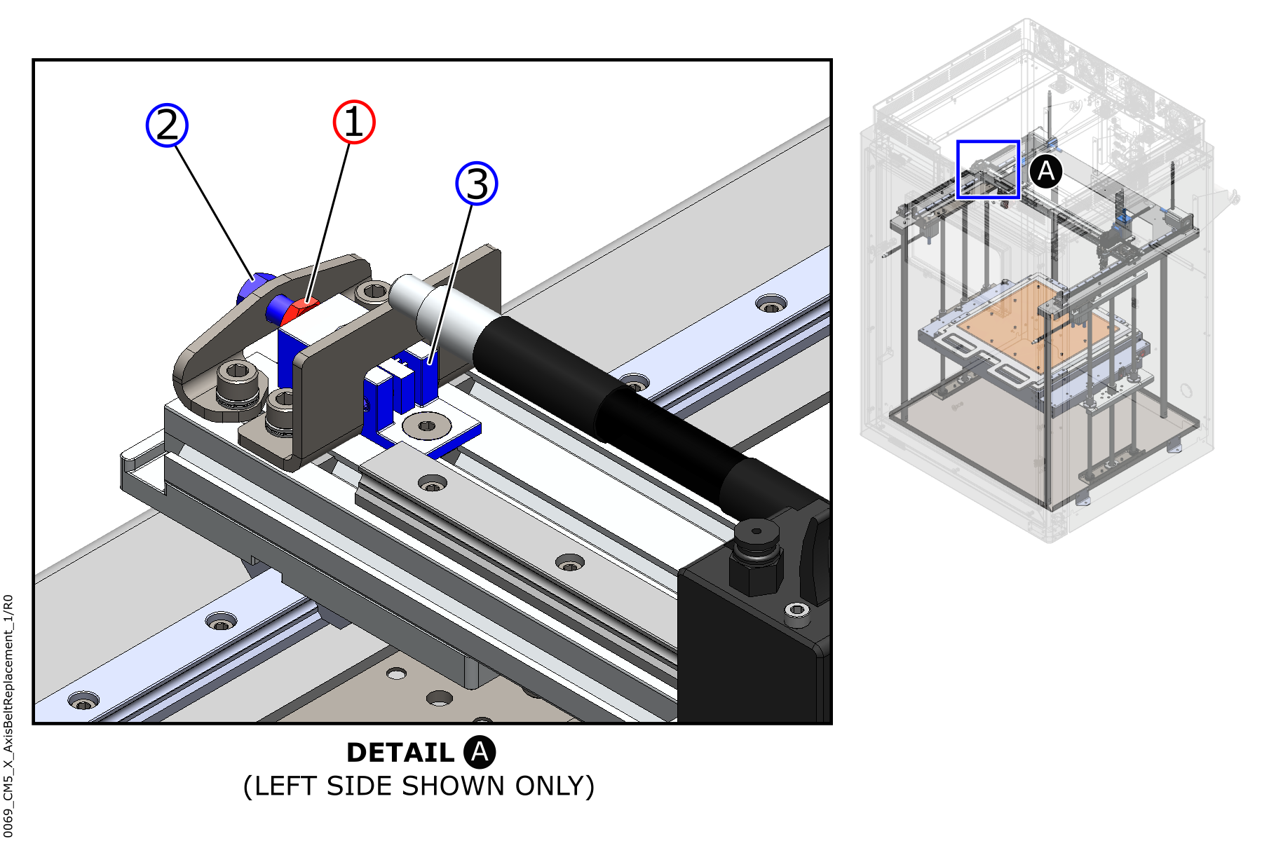
- If the machine has jam nut (1): Use the 10 mm wrench to loosen the jam nut (1) of the left X-axis belt block (3).
- Loosen the X-axis belt block tensioning screw (2) until there is no tension on the X-axis belt.
- Do steps 1 and 2 with the X-axis belt block (3) found on the right side of the machine.
- Make sure that there is no tension on the X-axis belt.
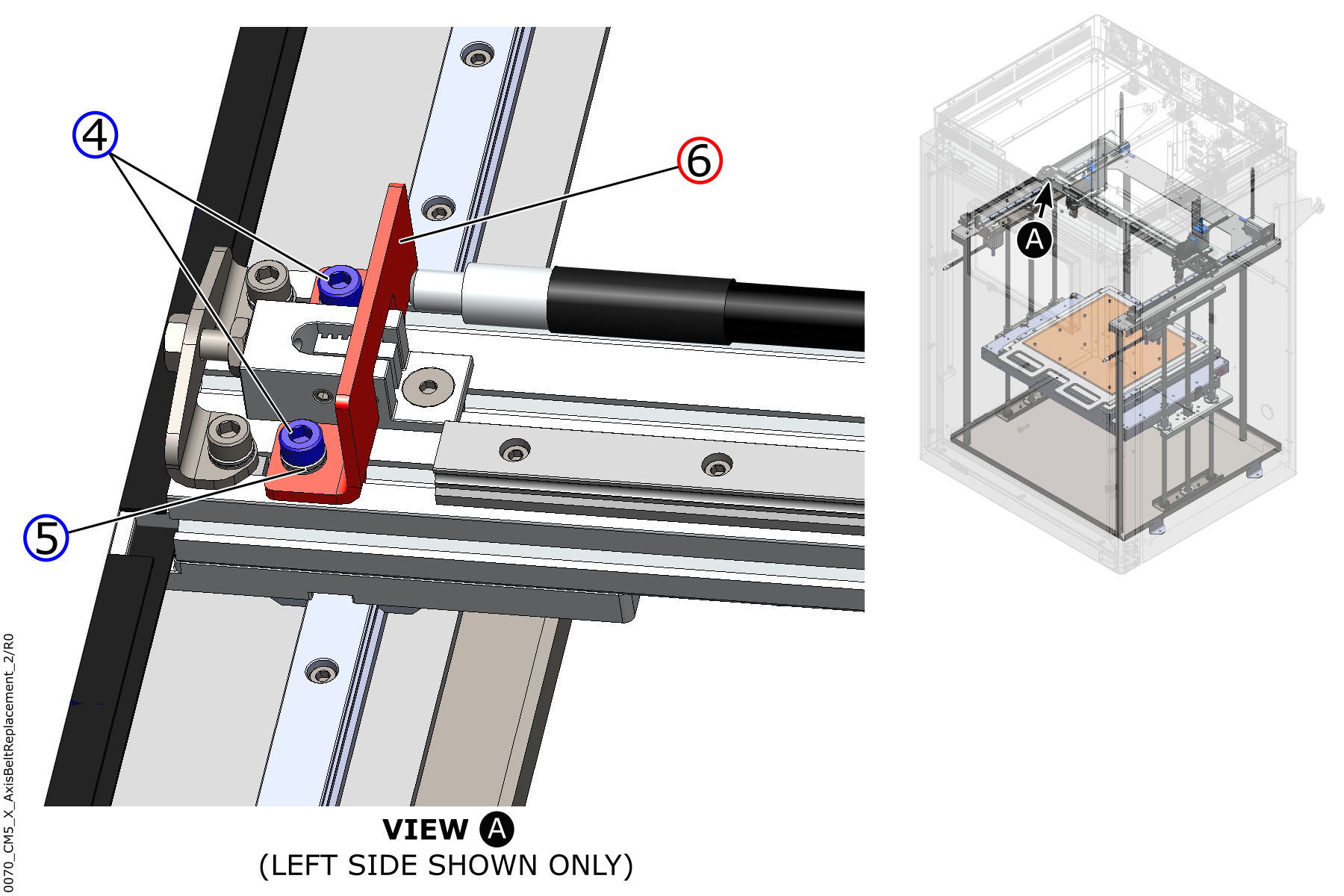
- Use the 4 mm hex key to remove the two screws (4) and the two lock washers (5).
- Discard the two lock washers (5).
- Remove the X-axis end stop bracket (6) from the machine.
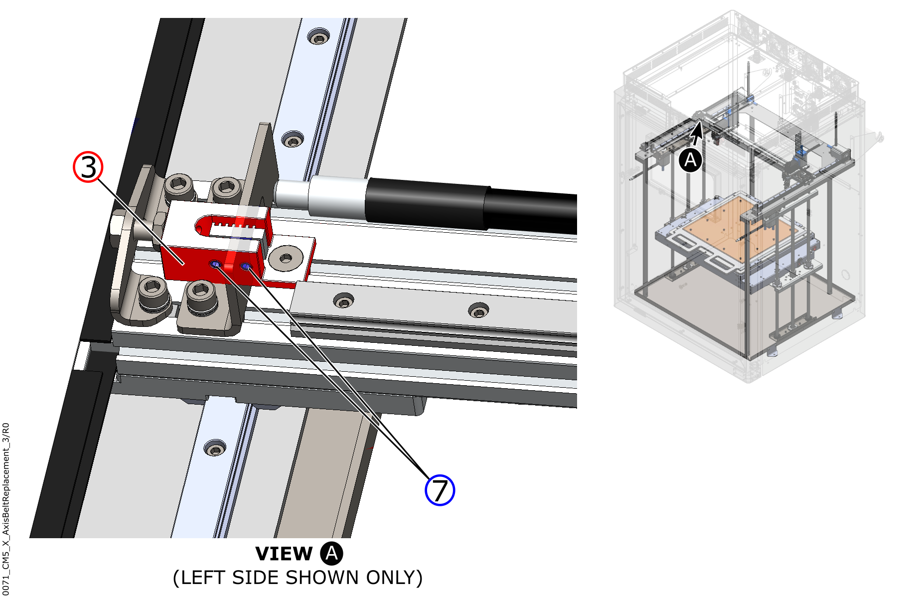
- Use the 2 mm hex key to loosen the two set screws (7) from the belt block (3).
- Do steps 5 to 8 for the components found on the right side of the machine.
- Remove the X-axis belt from the machine.
- Discard the X-axis belt.
Install the New X-Axis Belt
Tighten the screw(s) by hand unless a torque value is specified. Do not tighten the screw(s) too much. Failure to do so will cause damage to the component(s).
Make sure that the belt teeth correctly engage with the teeth of the machine components. Failure to do so can cause damage to the machine component(s).
- Put the end of the new X-axis belt in position in the left-side belt block (3).
- Use the 2 mm hex key to tighten the two set screws (7). Do not tighten the two set screws (7) too much.
- Make sure that the X-axis belt is tight in the X-axis belt block (3).
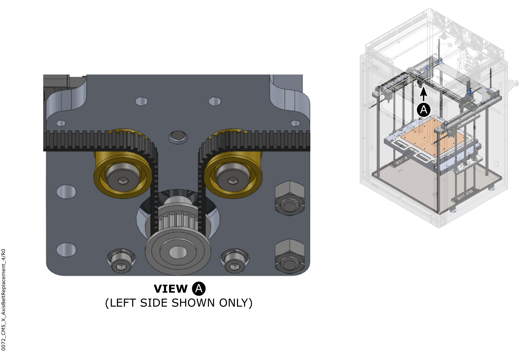
- Put the free end of the X-axis belt in position around the two idler pulleys and the X-axis motor drive pulley of the two toolheads.
- Install the free end of the X-axis belt into the belt block (3) found on the right side of the machine.
- Use the 2 mm hex key to tighten the two set screws (7). Do not tighten the two set screws (7) too much.
- Make sure that the X-axis belt is tight in the X-axis belt block (3).
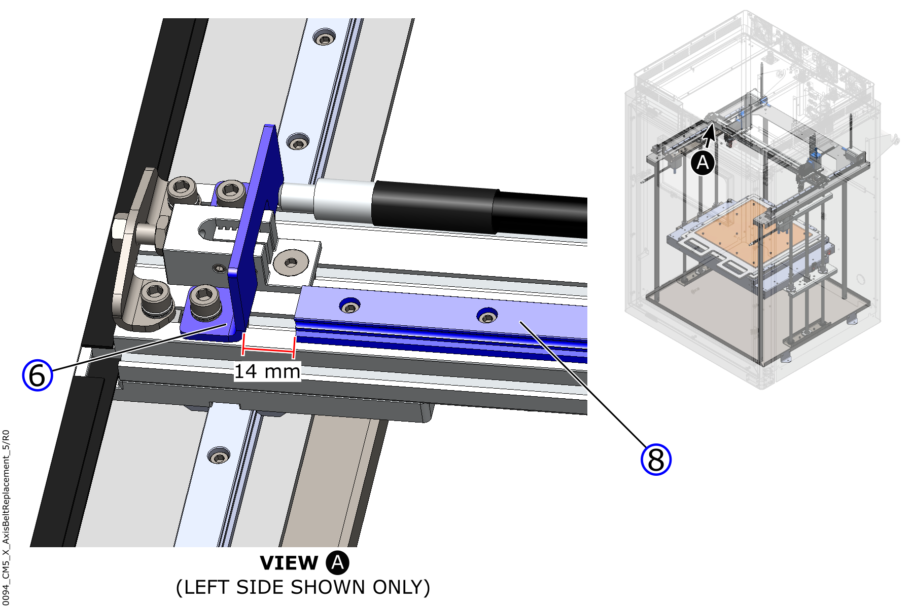
- Put the left X-axis end stop bracket (6) into position.
- Use the 4 mm hex key to install the two screws (4) and the two new lock washers (5) on the X-axis end stop bracket. Do not tighten the two screws (4) at this point in time.
- Use the tape measure, or ruler, to set the left X-axis end stop bracket (6) to a distance of 0.55 inch (14 mm) from where the X-axis linear rail (8) ends.
- Use the torque wrench, the 4 mm socket, and the 4mm hex bit to tighten the two screws (4) to 4 N·m.
- Do steps 9 to 11 for the X-axis end stop bracket (6) found on the right side of the machine.
- Adjust the tension of the X-axis belt. Refer to Inspect and Adjust XYZ-Axes Belt Tension.
Test and Return to Service
- Make sure that you remove all the tools from the build chamber.
- Close the build chamber door.
-
- For AON M2+ (CE) machines: Connect power to the machine from the local supply disconnecting device.
- For AON M2+ (R-NZ), AON M2+, AON-M2 2020 and AON-M2 machines: Connect the main power cord to the receptacle.
- Turn the power ON with the ON/OFF switch found on the rear panel of the the machine.
- Release the E-stop button.
- Home XYZ.