Replace Y-Axis Motors
| Model | [•] AON M2+ (CE) | [•] AON M2+ (R-NZ) | [•] AON M2+ | [•] AON-M2 2020 | [•] AON-M2 |
| Category | [ ] Preventive | [•] Corrective |
Summary
The procedure that follows gives the instructions on how to replace the two Y-axis motors.
Estimated time: 90 minutes
The Y-axis motor configurations are different between the AON M2+ (CE), the AON M2+ (R-NZ), the AON-M2 2020 and the AON-M2 models. See the instructions for the applicable configuration:
AON M2+ (CE), AON M2+ (R-NZ), AON-M2+ and AON-M2-2020 Machines
Tools
| Qty | Description | Specification |
|---|---|---|
| 1 | Camera, digital | N/A |
| 1 | Screwdriver | Flathead, small |
| 1 | Bucket | 3 liters minimum |
| 1 | Hex key | 3 mm |
| 1 | Hex key | 4 mm |
| 1 | Wrench | 8 mm |
| 1 | Wrench | 10 mm |
| 1 | Tape | Non-glossy |
| 1 | Marker | Black, fine tip |
| A/R | Rags | Lint-free |
| A/R | Isopropyl Alcohol | 99% |
Parts Information
| Qty | Part Number | Description |
|---|---|---|
| 1 | A-0302-005 | Y Motor Assy - Left (2020/M2+.) |
| 1 | A-0302-006 | Y Motor Assy - Right (2020/M2+.) |
| 1 | M2-SUB-WC-MTR-Y-L | M2 Y Motor and Cooling Block Sub-assembly, L/H (AON-M2) |
| 1 | M2-SUB-WC-MTR-Y-R | M2 Y Motor and Cooling Block Sub-assembly, R/H (AON-M2) |
| 2 | 2D91FE90 | Washer, M5 Nordlock, SS |
| 4 | HW-NUT-DIS-M5 | Top-Lock Locknut, M5 |
The Parts Information table gives the part numbers for the left and right side Y-axis motors. Only use the part applicable for your machine.
Reach out to our Customer Success team at help@aon3d.com for genuine AON3D replacement part(s).
To help with print quality and machine reliability, AON3D recommends to change the two Y-axis motors as a pair.
Personal Protective Equipment
| Qty | Description | Minimum Specification |
|---|---|---|
| 1 | Safety Eyewear | ANSI/ISEA Z87.1 |
| 1 | Safety Footwear | N/A |
| A/R | Nitrile Gloves | ISO 2859-1 or ASTM D6319 |
Prepare the Machine
Make sure that there are no prints on the build surface. Remove print(s) before the procedure that follows is started. Failure to do so can cause a collision and cause damage to the machine component(s).
- Home XYZ.
- Lower the Z-axis by 300 mm.
- Open the build chamber door.
- Push the E-stop button.
- Turn the power OFF with the ON/OFF switch found behind the machine.
-
- For AON M2+ (CE) machines: Disconnect power to the machine from the local supply disconnecting device.
- For AON M2+ (R-NZ), AON M2+ and AON-M2 2020 machines: Disconnect the main power cord from the receptacle.
- Wait until the build chamber, build platform and hot ends are at room temperature.
Remove the Y-Axis Motors
Wait until all the machine components are at room temperature before you continue. Some machine components can be hot if the machine was recently used. Failure to do so can cause injuries.
- Manually move the two toolhead assemblies on the X-axis to the opposite side of the Y-axis motor that is to be replaced.
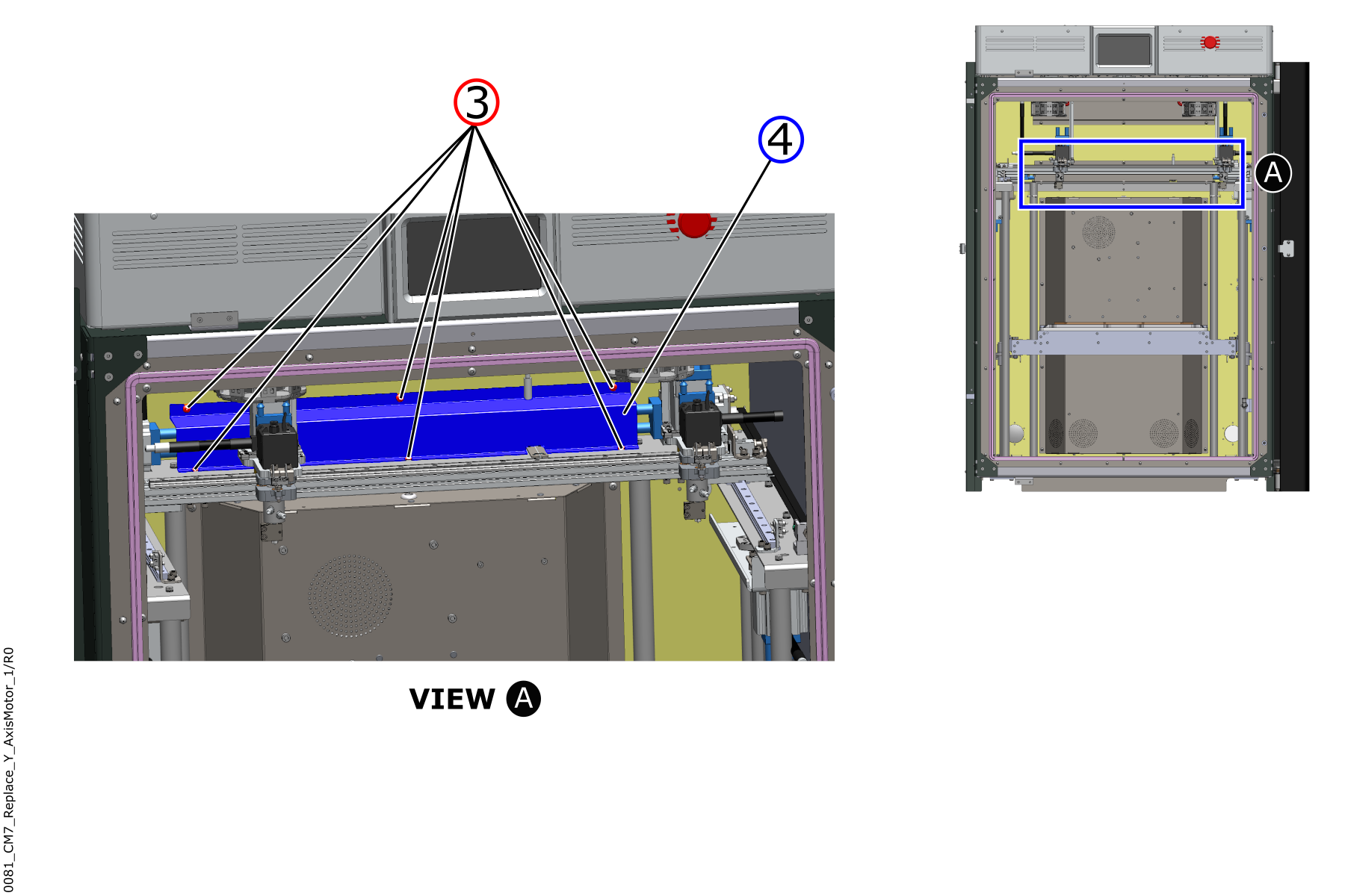
- Use the 3 mm hex key to remove the six screws (3) from the Y-axis vanity cover (4).
- Remove the Y-axis vanity cover (4) from the machine.
- Use the non-glossy tape and the marker to correctly identify the power cable that connects to the Y-axis motor (5).
- Disconnect the power cable from the Y-axis motor (5).
Be careful when the coolant tube clamps are removed. The coolant tubes are soft and the two coolant tube clamps can be sharp.
- Disconnect the two coolant tubes from the Y-axis motor (5) cooling block inlet and outlet ports as follows:
- Put the 3-liter bucket below the Y-axis motor (5).
- Use the non-glossy tape and the marker to correctly identify the two coolant tubes attached to the Y-axis motor (5) cooling block inlet and outlet ports.
- Use the small flathead screwdriver to loosen the screws found on the two coolant tube clamps.
- Use the non-glossy tape to attach the loose coolant tube clamps on the two coolant tubes.
- Remove the two coolant tubes from the Y-axis motor (5) cooling block inlet and outlet ports.
- Put the two coolant tubes into the 3-liter bucket to prevent spills.
- Use a lint-free rag and isopropyl alcohol to clean the coolant in the build chamber, if necessary.
- Remove the Y-axis belt (8) as follows:
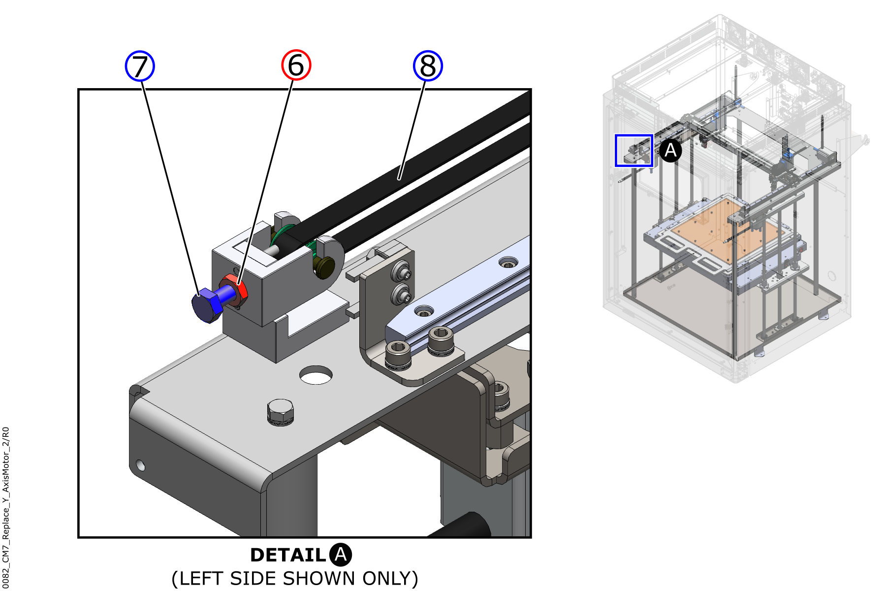
- Use the 10 mm wrench to loosen the Y-axis idler jam nut (6).
- Loosen the Y-axis idler tension screw (7) until there is no tension on the Y-axis belt (8).
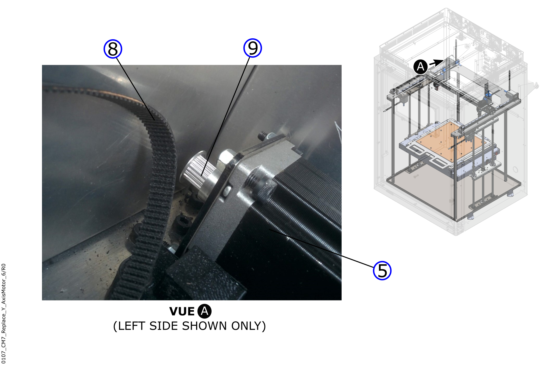
- Remove the Y-axis belt (8) from the Y-axis motor pulley (9).
- Inspect the Y-axis belt (8) for wear. Replace as necessary. Refer to Replace Y-Axis Belts.
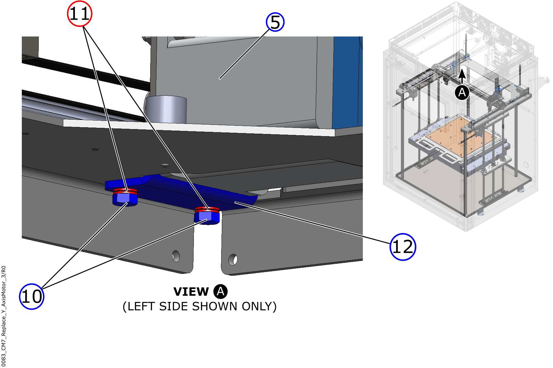
- Use the 8 mm wrench to remove the two screws (10) and the two lock washers (11) from the Y-axis motor bracket (12).
- Discard the two lock washers (11).
- Carefully remove the Y-motor bracket (12) and the Y-axis motor (5) assembly from the machine.
Use the digital camera to take a photograph of the orientation of the Y-axis motor (5) on the Y-axis motor bracket (12), if necessary.
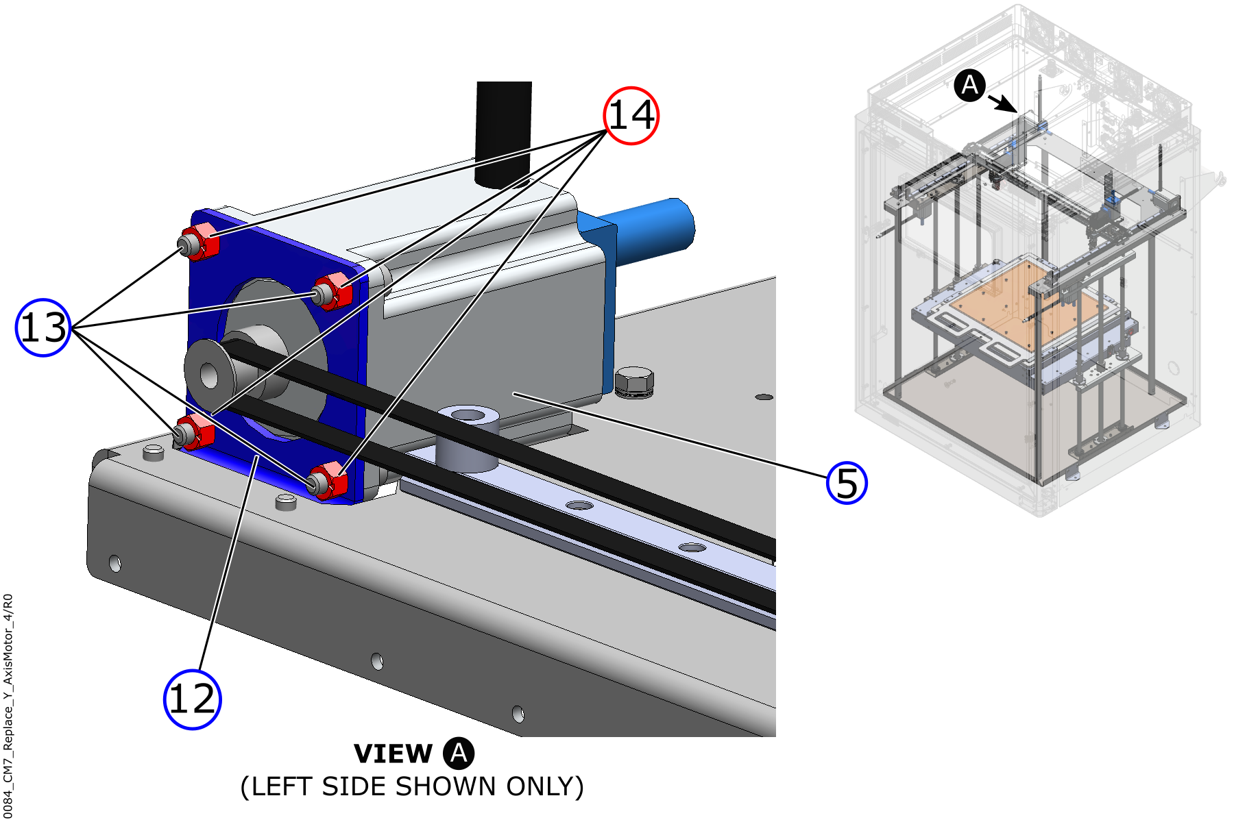
- Use the 4 mm hex key, and the 8 mm wrench, to remove the four screws (13) and the four locknuts (14).
- Discard the four locknuts (14).
- Remove the Y-axis motor (5) from the motor bracket (12).
- Discard the Y-axis motor (5) in accordance with the local laws and/or regulations.
- Do steps 1 to 14 for the adjacent Y-axis motor, if necessary.
Install the New Y-Axis Motors
Make sure that the new Y-axis motor (5) configuration is correct (left or right). To identify the configuration, look at the motor with the cooling block inlet and outlet ports in front of you, and the wires pointing down:
• On the left Y-axis motor (5): The coolant block inlet and outlet ports, found on top, must point to the left.
• On the right Y-axis motor (5): The coolant block inlet and outlet ports, found on top, must point to the right.
Tighten the screw(s) by hand unless a torque value is specified. Do not tighten the screw(s) too much. Failure to do so can cause damage to the machine component(s).
Look at the digital photograph of the Y-axis motor (5) orientation to use as a reference.
- Install the new Y-axis motor (5) into the Y-axis motor bracket (12) as follows:
- Use a lint-free rag and isopropyl alcohol to clean the Y-axis motor bracket (12), if necessary.
- Let the clean surfaces dry for two minutes.
- Put the Y-axis motor (5) in position into the Y-axis motor bracket (12). Make sure that the Y-axis motor bracket (12) lower tab is put in position on the outside of the Y-axis motor (5) and that the power cable points up.
- Install the four screws (13) through the Y-axis motor (5) holes and into the Y-axis motor bracket (12) holes.
- Install the four new locknuts (14) onto the four screws (13),
- Use the 4 mm hex key and the 8 mm wrench to tighten the four screws (13) and four locknuts (14).
- Install one new Nordlock® lock washer (11) onto one screw (10). Do this step for the two screws (10).
- Put the Y-axis motor (5) and Y-axis motor bracket (12) assembly in position into the top plate, at the rear of the machine.
- Make sure that the Y-axis motor bracket (12) is in position below the top plate.
- Install the two screws (10) and the two Nordlock® lock washers, through the Y-axis motor bracket (12), and into the top plate.
- Use the 8 mm wrench to tighten the two screws (10).
Make sure that the Y-axis belt (8) teeth engage correctly with the teeth of the Y-axis motor pulley (9). Failure to do so can cause damage to the machine component(s).
- Install the Y-axis belt (8) onto the Y-axis motor pulley (9). Refer to Replace Y-Axis Belts.
Make sure that the Y-axis belt is installed straight, with no twists, no kinks, and/or no loops. Failure to do so will cause irregular print quality and/or will cause damage to the machine component(s).
- Install the coolant tubes onto the Y-axis motor (5) cooling block inlet and outlet ports as follows:
Be careful when the coolant tube clamps are installed. The coolant tubes are soft and the two coolant tube clamps can be sharp.
- Use the identification label(s) to put the coolant tubes in position onto the Y-axis motor (5) cooling block inlet and outlet ports.
- Remove and discard the identification label(s).
- Put the coolant tube clamps in position onto the Y-axis motor (5) cooling block inlet and outlet ports.
- Use the small flathead screwdriver to tighten the screw of the two coolant tube clamps. Do not tighten too much.
- Use the identification label(s) to connect the power cable to the Y-axis motor (5).
- Remove and discard the identification label(s).
- Put the vanity cover (4) in position at the rear of the machine, onto the rear interior panel.
- Manually install the six screws (3) through the vanity cover, and into the rear interior panel.
- Use the 3 mm hex key to tighten the six screws (3).
- Adjust the Y-axis belt tension. Refer to Inspect and Adjust XYZ-Axes Belt Tension.
- Do steps 1 to 9 for the adjacent Y-axis motor, if necessary.
- Fill the cooling system, if necessary. Refer to Inspect Coolant Level.
Test and Return to Service
- Make sure that you remove all the tools from the build chamber.
- Close the build chamber door.
-
- For AON M2+ (CE) machines: Connect power to the machine from the local supply disconnecting device.
- For AON M2+ (R-NZ), AON M2+ and AON-M2 2020 machines: Connect the main power cord to the receptacle.
- Turn the power ON with the ON/OFF switch found on the rear panel of the machine.
- Release the E-stop button.
- Home XYZ.
AON-M2 Machines
Tools
| Qty | Description | Specification |
|---|---|---|
| 1 | Camera, digital | N/A |
| 1 | Screwdriver | Flathead, small |
| 1 | Bucket | 3 liters minimum |
| 1 | Hex key | 3 mm |
| 1 | Hex key | 4 mm |
| 1 | Wrench | 8 mm |
| 1 | Wrench | 10 mm |
| 1 | Tape | Non-glossy |
| 1 | Marker | Black, fine tip (recommended) |
| A/R | Rags | Lint-free |
| A/R | Isopropyl alcohol | 99% |
Parts Information
| Qty | Part Number | Description |
|---|---|---|
| 1 | M2-SUB-WC-MTR-Y-L | M2 Y Motor and Cooling Block Sub-assembly, L/H |
| 1 | M2-SUB-WC-MTR-Y-R | M2 Y Motor and Cooling Block Sub-assembly, R/H |
| 3 | HW-WASH-LCK-SPLT-M5-SS | M5 Split Lock Washer, SS |
| 4 | HW-NUT-DIS-M5 | Top-Lock Locknut, M5 |
The Parts Information table gives the part numbers for the left and right side Y-axis motors. Only use the part applicable for your machine.
Reach out to our Customer Success team at help@aon3d.com for genuine AON3D replacement part(s) inquiries.
Personal Protective Equipment
| Qty | Description | Minimum Specification |
|---|---|---|
| 1 | Safety Eyewear | ANSI/ISEA Z87.1 |
| 1 | Safety Footwear | N/A |
| A/R | Nitrile Gloves | ISO 2859-1 or ASTM D6319 |
Prepare the Machine
Make sure that there are no prints on the build surface. Remove print(s) before the procedure that follows is started. Failure to do so can cause a collision and cause damage to the machine component(s).
- Home XYZ.
- Lower the Z-axis by 300 mm.
- Push the E-stop button.
- Open the build chamber door.
- Turn the power OFF with the ON/OFF switch found behind the machine.
- Disconnect the main power cord from the receptacle.
- Wait until the build chamber, build platform and hot ends are at room temperature.
Remove the Y-Axis Motors
Wait until all the machine components are at room temperature before you continue. Some machine components can be hot if the machine was recently used. Failure to do so can cause injuries.
- Manually move the two toolhead assemblies on the X-axis to the opposite side of the Y-axis motor that is to be replaced.
- Use the non-glossy tape and the marker to identify the power cable that connects to the Y-axis motor (5).
- Disconnect the power cable from the Y-axis motor (5).
Be careful when you install and/or remove the coolant tube clamps. The coolant tubes are soft and the coolant tube clamps can be sharp. Failure to do so can cause damage to the machine components.
- Disconnect the two coolant tubes from the Y-axis motor (5) cooling block as follows:
- Put the 3-liter bucket below the Y-axis motor (5).
- Use the non-glossy tape and the marker to correctly identify the two coolant tubes attached to the Y-axis motor (5) cooling block inlet and outlet ports.
- Use the small flathead screwdriver to loosen the screws found on the two coolant tube clamps.
- Use the non-glossy tape to attach the loose coolant tube clamps on the two coolant tubes.
- Remove the two coolant tubes from the Y-axis motor (5) cooling block inlet and outlet ports.
- Put the two coolant tubes into the 3-liter bucket to prevent spills.
- Use a lint-free rag and isopropyl alcohol to clean the coolant in the build chamber, if necessary.
- Remove the Y-axis belt (8) as follows:
- Use the 10 mm wrench to loosen the Y-axis idler jam nut (6).
- Loosen the Y-axis idler tension screw (7) until there is no tension on the Y-axis belt (8).
- Remove the Y-axis belt (8) from the Y-axis motor pulley (9).
- Inspect the Y-axis belt (8) for wear. Replace as necessary. Refer to Replace Y-Axis Belts.
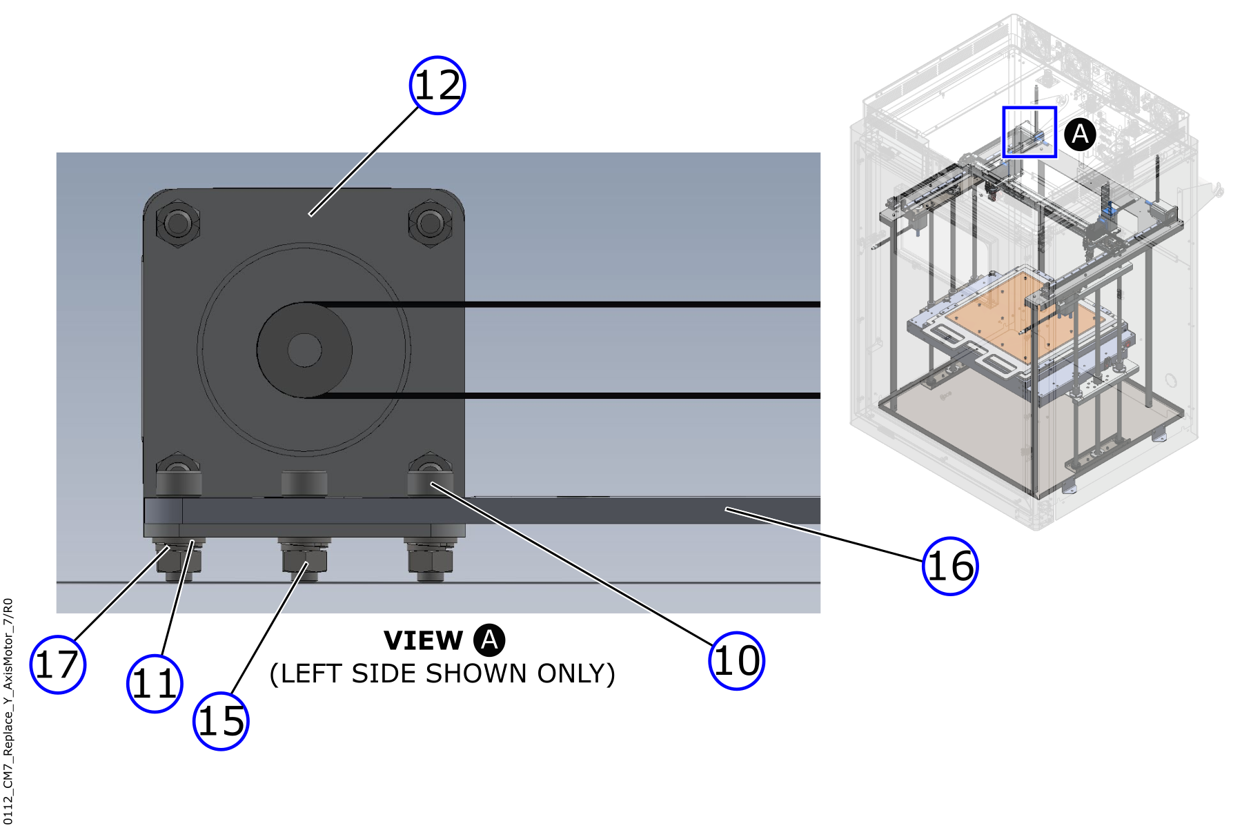
- Use the 4 mm hex key and the 8 mm wrench to remove the fasteners to disassemble the Y-axis motor (5) from the Y-axis motor bracket (12):
- Three screws (10)
- Three flat washers (11)
- Three lock washers (17)
- Three nuts (15).
- Discard the three lock washers (17).
- Carefully remove the Y-motor bracket (12) and the Y-axis motor (5) assembly from the machine.
Use the digital camera to take a photograph of the orientation of the Y-axis motor (5) on the Y-axis motor bracket (12), if necessary.
- Use the 4 mm hex key and the 8 mm wrench to remove the four screws (13) and the four locknuts (14).
- Discard the four locknuts (14).
- Remove the Y-axis motor (5) from the Y-axis motor bracket (12).
- Discard the Y-axis motor (5) in accordance with the local laws and/or regulations.
- Do steps 1 to 12 for the adjacent Y-axis motor, if necessary.
Install the New Y-Axis Motors
Make sure that the new Y-axis motor (5) configuration is correct (left or right). To identify the configuration, look at the motor with the cooling block inlet and outlet ports in front of you, and the wires pointing down:
• On the left Y-axis motor (5): The coolant block inlet and outlet ports, found on top, must point to the left.
• On the right Y-axis motor (5): The coolant block inlet and outlet ports, found on top, must point to the right.
Tighten the screw(s) by hand unless a torque value is specified. Do not tighten the screw(s) too much. Failure to do so can cause damage to the machine component(s).
Look at the digital photograph of the Y-axis motor (5) orientation to use as a reference.
- Install the new Y-axis motor (5) into the Y-axis motor bracket (12) as follows:
- Use a lint-free rag and isopropyl alcohol to clean the Y-axis motor bracket (12), if necessary.
- Let the clean surfaces dry for two minutes.
- Put the Y-axis motor (5) in position into the Y-axis motor bracket (12). Make sure that the Y-axis motor bracket (12) lower tab is put in position on the external side of the Y-axis motor (5), and that the power cable points up.
- Install the four screws (13) through the Y-axis motor (5) holes, and into the Y-axis motor bracket (12) holes.
- Install the four new locknuts (14) onto the four screws (13),
- Use the 4 mm hex key, and the 8 mm wrench, to tighten the four screws (13) and four locknuts (14).
- Put the Y-axis motor (5) and Y-axis motor bracket (12) assembly in position into the top plate (16), at the rear of the machine.
- Make sure that the Y-axis motor bracket (12) tab is in position below the top plate (16).
- Install the three screws (10) from the top of the top plate (16).
- Install the fasteners that follow onto the three screws (10) to assemble the Y-axis motor (5) and Y-axis motor bracket (12) assembly onto the top plate (16):
- Three flat washers (11).
- Three new lock washers (17).
- Three nuts (15).
- Use the 4 mm hex key and the 8 mm wrench to tighten the three screws (10) and the three nuts (15).
Make sure that the Y-axis (8) belt teeth engage correctly with the teeth of the Y-axis motor pulley (9). Failure to do so can cause damage to the machine component(s).
- Install the Y-axis belt (8) onto the Y-axis motor pulley (9). Refer to Replace Y-Axis Belts.
Make sure that the Y-axis belt (8) is installed straight, with no twists, no kinks, and/or no loops. Failure to do so can cause irregular print quality and/or can cause damage to the machine component(s).
- Install the coolant tubes onto the Y-axis motor (5) cooling block inlet and outlet ports as follows:
Be careful when the coolant tube clamps are installed. The coolant tubes are soft and the two coolant tube clamps can be sharp.
- Use the identification label(s) to put the coolant tubes in position onto the Y-axis motor (5) cooling block inlet and outlet ports.
- Remove and discard the identification label(s).
- Put the coolant tube clamps in position over the Y-axis motor (5) coolant tubes.
- Use the small flathead screwdriver to tighten the screws of the two coolant tube clamps. Do not tighten too much.
- Use the identification label(s) to connect the power cable to the Y-axis motor (5).
- Remove and discard the identification label(s).
- Adjust the Y-axis belt tension. Refer to Inspect and Adjust XYZ-Axes Belt Tension.
- Do steps 1 to 12 for the adjacent Y-axis motor, if necessary.
- Fill the cooling system, if necessary. Refer to Inspect Coolant Level.
Test and Return to Service
- Make sure that you remove all the tools from the build chamber.
- Close the build chamber door.
- Connect the main power cord to the receptacle.
- Turn the power ON with the ON/OFF switch found on the rear panel of the machine.
- Release the E-stop button.
- Home XYZ.