Solvay KetaSpire® PEEK
Polyetheretherketone (PEEK) is a semi-crystalline thermoplastic polymer commonly used to replace metal components in severe end-use environments. Solvay KetaSpire® PEEK filament provides high fatigue and chemical resistance with excellent mechanical properties that are retained at high operational temperatures.
Printing Difficulty: Challenging/Expert
KetaSpire® PEEK can be purchased from AON3D directly by contacting help@aon3d.com.
- Moisture Control
- Build Platform Adhesion
- General Process Settings
- Post-Processing
- Technical Specifications
- Troubleshooting
Moisture Control
KetaSpire® PEEK is extremely susceptible to moisture uptake. Bubbles, popping noises, excessive oozing, and stringing may occur if it has been hydrated.
The filament can be dried in a convection oven at 120ºC for at least 4 hours before processing and fed from a low humidity environment. When not in use, store in a sealed package or container with silica desiccant to inhibit moisture absorption. Our filament dry storage and feed system setup prevents filament moisture uptake to keep the material printing process free of moisture, contact help@aon3d.com for more information.
For more information, see the Filament Drying and Moisture Control page.
Build Platform Adhesion
For instructions on how to inspect the AON3D build plates, refer to the Inspect and Clean Build Plates procedure.
Garolite G-10 Build Sheet
KetaSpire® PEEK prints best on the Garolite G-10 build sheet.
CF-PEEK Composite Plate
KetaSpire® PEEK prints well on the CF-PEEK composite plate.
First Layer Adhesion
To successfully print KetaSpire® PEEK on the CF-PEEK composite plate and Garolite G-10 build sheet, reduce the First Layer Speed and slightly increase the extrusion temperature for the first layer. Increase the First Layer Height and First Layer Width above 120%.
The first layer adhesion strength may not be enough to prevent warping at warp-prone geometries. If needed, a sacrificial temperature gradient raft can increase first layer adhesion. However, if the temperature gradient is very large, a lot of uneven crystallization may occur and cause warping.
The first few layers of the part may be printed at higher extrusion temperatures, slowly tapering off to overall extrusion temperatures if needed. Start with a First Layer Height and First Layer Width of 100-150% for both and adjust until desired bed adhesion is achieved.
| First Layer Extrusion Temperature | First Layer Speed |
|---|---|
| 430-450ºC | 20-25 mm/s |
Warping may be very challenging to control when printing on the CF-PEEK composite plate. Avoid increasing the first layer extrusion temperature too high to increase first layer adhesion. Extremely high extrusion temperatures may cause rapid crystallization, leading to extreme warping, deformation, and poor interlayer welding strength. Anchors may be added to the sides of the part to minimize warping by increasing the total surface area on the build platform. Geometries such as pyramids or tabs can be used as anchors.
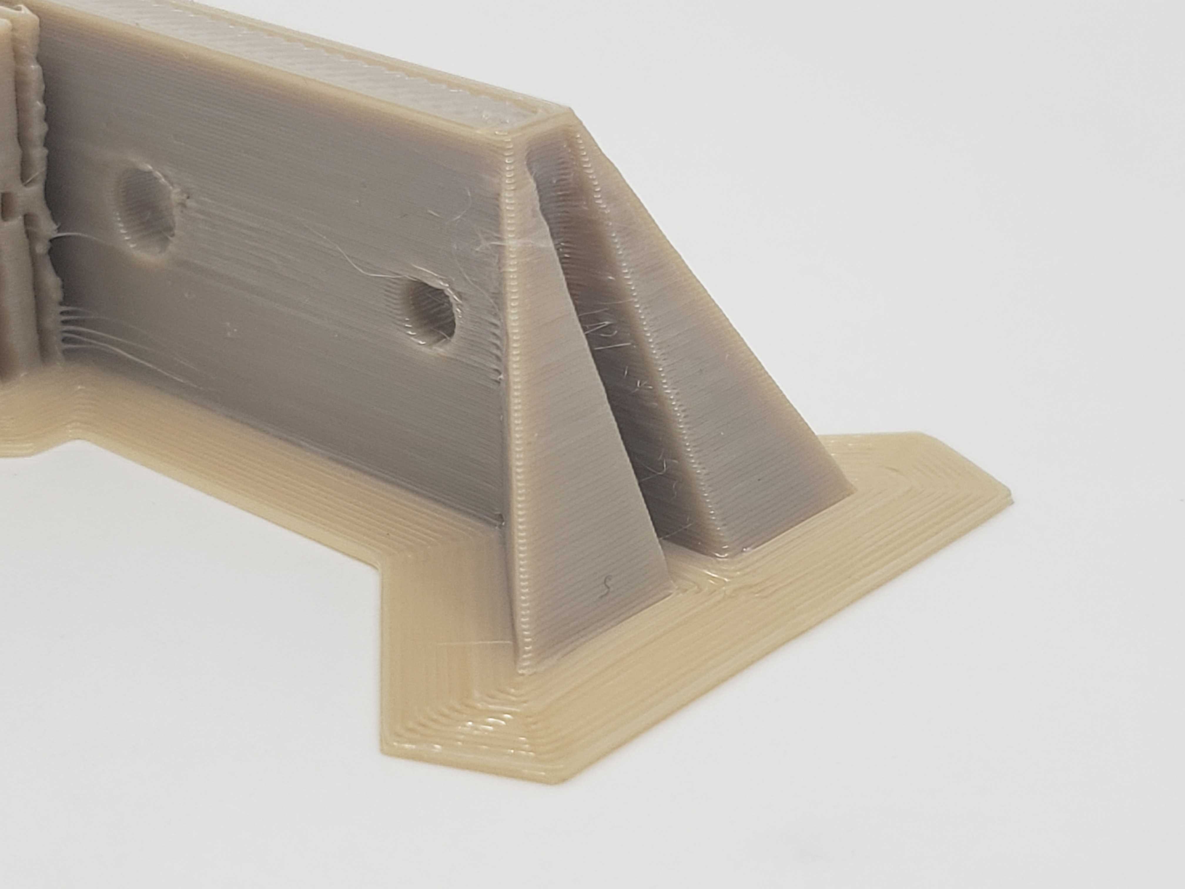
As shown above, two upright pyramid anchors have been added to the corners of a warp-prone geometry. Critical areas of the geometry are anchored to the build platform.
For more information, see the Build Platform Adhesion guide.
High-Temperature Build Plate
KetaSpire® PEEK prints best on the High-Temperature Build Plate.
First Layer Settings
Part and/or build platform damage may occur during part removal. If needed, a sacrificial temperature gradient raft can facilitate part removal. The first layer may be thick and can be printed at a lower extrusion temperature that provides adequate bed adhesion but allows for easy part removal. If required, the extrusion temperature can be gradually increased in the raft to optimal extrusion temperatures. Fine-tuning the temperature gradient and printing speed will make the part release from the raft easily. Printing the raft this way will compensate for toolhead expansion. Increasing/decreasing thick and thin raft layers will affect raft ease of removal.
For example, the table below illustrates a possible temperature gradient using a raft with 2 thick and 4 thin layers for semi-crystalline printing:
| Layer Number | Extrusion Temperature | Raft Layer Type |
|---|---|---|
| 1 | 380ºC | Base - Thick |
| 2 | 385ºC | Base - Thick |
| 3 | 390ºC | Top - Thin |
| 4 | 395ºC | Top - Thin |
| 5 | 400ºC | Top - Thin |
| 6 | 405ºC | Top - Thin |
| 7 | 410ºC | First Layer of Part |
| 8 | 410ºC | Second Layer of Part |
As shown above, the first Thick raft layer extrusion temperature is decreased to reduce part and/or build platform damage during part removal. The extrusion temperature is then increased for the First Layer of Part to increase the adhesion between the part and raft. The layers in the part are then extruded at extrusion temperatures where optimal interlayer welding strength and a reduced stress gradient in the part are achieved.
Start with a First Layer Height and First Layer Width of 100-150% for both and adjust until desired bed adhesion is achieved.
| First Layer Extrusion Temperature | First Layer Speed |
|---|---|
| 390-410ºC | 20-25 mm/s |
However, if adequate first layer adhesion is difficult to achieve without warping, avoid increasing the first layer extrusion temperature too high. High extrusion temperatures may cause rapid crystallization, leading to extreme warping, deformation, and poor interlayer welding strength. Anchors may be added to the sides of the part to minimize warping by increasing the total surface area on the build platform. Geometries such as pyramids or tabs can be used as anchors.
As shown above, two upright pyramid anchors have been added to the corners of a warp-prone geometry. Critical areas of the geometry are anchored to the build platform.
For more information, see the Build Platform Adhesion guide.
High-Temperature Build Plate
KetaSpire® PEEK prints best on the High-Temperature Build Plate.
First Layer Settings
Part and/or build platform damage may occur during part removal. If needed, a sacrificial temperature gradient raft can facilitate part removal. The first layer may be thick and can be printed at a lower extrusion temperature that provides adequate bed adhesion but allows for easy part removal. If required, the extrusion temperature can be gradually increased in the raft to optimal extrusion temperatures. Fine-tuning the temperature gradient and printing speed will make the part release from the raft easily. Printing the raft this way will compensate for toolhead expansion. Increasing/decreasing thick and thin raft layers will affect raft ease of removal.
For example, the table below illustrates a possible temperature gradient using a raft with 2 thick and 4 thin layers for semi-crystalline printing:
| Layer Number | Extrusion Temperature | Raft Layer Type |
|---|---|---|
| 1 | 380ºC | Base - Thick |
| 2 | 385ºC | Base - Thick |
| 3 | 390ºC | Top - Thin |
| 4 | 395ºC | Top - Thin |
| 5 | 400ºC | Top - Thin |
| 6 | 405ºC | Top - Thin |
| 7 | 410ºC | First Layer of Part |
| 8 | 410ºC | Second Layer of Part |
As shown above, the first Thick raft layer extrusion temperature is decreased to reduce part and/or build platform damage during part removal. The extrusion temperature is then increased for the First Layer of Part to increase the adhesion between the part and raft. The layers in the part are then extruded at extrusion temperatures where optimal interlayer welding strength and a reduced stress gradient in the part is achieved.
Start with a First Layer Height and First Layer Width of 100-150% for both and adjust until desired bed adhesion is achieved.
| First Layer Extrusion Temperature | First Layer Speed |
|---|---|
| 390-410ºC | 20-25 mm/s |
However, if adequate first layer adhesion is difficult to achieve without warping, avoid increasing the first layer extrusion temperature too high. High extrusion temperatures may cause rapid crystallization, leading to extreme warping, deformation, and poor interlayer welding strength. Anchors may be added to the sides of the part to minimize warping by increasing the total surface area on the build platform. Geometries such as pyramids or tabs can be used as anchors.
As shown above, two upright pyramid anchors have been added to the corners of a warp-prone geometry. Critical areas of the geometry are anchored to the build platform.
For more information, see the Build Platform Adhesion guide.
General Process Settings
For best results, process settings should be adjusted based on model geometry. If you require process development support, our Applications Engineering team can help! Send us a message at help@aon3d.com to consult with one of our Additive Manufacturing Specialists.
High semi-crystalline extrusion temperatures print best on the AON M2+ due to improved first layer adhesion on the CF-PEEK composite plate. Low amorphous extrusion temperatures may be difficult to achieve adequate first layer adhesion.
| Setting | AON M2+ | AON-M2 2020 | AON-M2 |
|---|---|---|---|
| Extrusion Temperature | 390-465ºC | 390-465ºC | 390-465ºC |
| Bed Temperature | 150ºC | 210ºC | 210ºC |
| Chamber Temperature | 135ºC | 135ºC | 120ºC* |
| Print Speed | 20-45 mm/s | 20-45 mm/s | 20-45 mm/s |
| Nozzle Size | 0.25-0.60 mm | 0.25-0.60 mm | 0.25-0.60 mm |
| Preferred Build Platform | Garolite G-10 Build Sheet | High-Temperature Build Plate | High-Temperature Build Plate |
*The AON-M2 is unable to reach chamber temperatures above 120ºC. This constraint may limit your ability to optimally print KetaSpire® PEEK semi-crystalline. The AON-M2 2020 and AON M2+ can reach chamber temperatures up to 135ºC, contact AON3D directly at help@aon3d.com for more information.
Processing conditions have a great influence on the degree of crystallinity, affecting the mechanical properties a part may have: managing crystallization is hard. We recommend two methods of printing KetaSpire® PEEK:
-
Print with a low-temperature environment: amorphous printing. The chamber temperature should be set below its crystallization temperature, likely below its glass transition temperature. The print will be mostly amorphous with good layer bonding, but annealing will be required afterward. Extrusion temperatures must be high enough to extrude molten material and melt the previous layer without immediately crystallizing when deposited. Annealing amorphous parts risk serious warping and deformation from crystallization-induced non-isometrical shrinkage. The more you have to crystalize in the annealing process, the more likely the part is to deform and warp.
-
Print with a very high-temperature environment and high extrusion temperature: semi-crystalline printing. The chamber should be set above its crystallization temperature, ideally at temperatures where peak crystallization rates occur. Previous layers will remelt from the nozzle as it moves over it, allowing for some intermixing of the layers before the material crystallizes. If the layers do not mix before crystallizing, they will not stick together. Annealing is not required but recommended to complete crystallization of the material. However, it is impossible to print KetaSpire® PEEK fully crystalline without an annealing process. A semi-crystalline part is far less likely to deform when annealed.
Amorphous extrusions are brownish-translucent, whereas crystallized extrusions are beige-opaque. If the finished part shows brown-translucent extrusions while printing semi-crystalline, see the Incomplete Crystallization section. Interlayer welding strength is related to the extrusion temperature, the higher the better. However, the formation of crystals at the surface of each extrusion from higher crystallization rates due to higher extrusion temperatures may decrease interlayer welding strength.
Crystallization rates can be controlled by optimizing toolhead paths when printing semi-crystalline. Improved interlayer welding strength is a balance of process parameters (Default Printing Speed, Internal Fill Pattern, etc.) to ensure desired crystallization rates. The amount of heat each extrusion experiences from each corresponding toolhead path and extrusion may affect crystallization rates. For example, localized infill regions with toolhead paths that occur over extended periods may cause uneven crystallization. Very slow toolhead paths may also cause rapid crystallization from the accumulation of heat.
For more information about PEEK crystallization, see our PEEK article.
Limit the use of KetaSpire® PEEK to small parts or low-mass parts (low infill, <20%, or made of only thin walls, 1-3 mm). Larger models of high infill percentages may warp, shrink, and/or deform due to the fast crystallization rate.
Use a nozzle size of at least 0.25mm with moderate printing speeds between 20-45 mm/s for optimal mechanical properties and print quality.
Avoid large flat surfaces parallel to the bed to avoid warping.
Larger parts can be printed with a 0.40-0.60mm nozzle at a layer height of 0.10-0.20mm for most applications.
Smaller parts can be printed with a 0.25mm nozzle at a layer height of 0.10-0.15mm.
Dual Extrusion and Support
There is currently no compatible support material for KetaSpire® PEEK; prints require self-support. For easy support removal and good support top/bottom contact layer adhesion, use only 1 Upper/Lower Vertical Separation Layer. More than 1 separation layer may risk the supported region of the part to detach and warp.
For more information, see the Using Supports and Support Materials guide.
Sample Slicer Profiles
SuperSlicer
All AON3D-validated materials are available in the SuperSlicer configuration bundle. Refer to SuperSlicer Installation and Update to install and update the SuperSlicer software. Follow the instructions to update to the latest version to ensure you have access to all available materials.
Simplify3D®
Simplify3D® sample profiles for KetaSpire® PEEK Prime are available in the Downloadable Assets section.
Post-Processing
Allow all machine components to reach room temperature before proceeding further. Failure to allow components to cool down will result in thermal injury (burns) to personnel.
Shrinkage, deformation, and warpage due to thermal shock may occur from removing the part before letting the machine cool. Instructions for removing the part from the build platform and additional support material can be found on the Build Platform Adhesion and Using Supports and Support Materials guides.
Garolite G-10 Build Sheet
KetaSpire® PEEK may parts separate easily from the Garolite G-10 build sheet by hand at room temperature. The use of a spatula can facilitate part removal if needed.
CF-PEEK Composite Plate
KetaSpire® PEEK may parts separate easily from the CF-PEEK composite plate by hand at room temperature. The use of a spatula can facilitate part removal if needed.
If there are multiple parts on the composite plate, remove the composite plate from the machine before removing the parts. Whereas if the print consists of multiple large/heavy or tall parts, it will be preferable to remove them from the composite plate before removing the sheet from the machine.
High-Temperature Build Plate
KetaSpire® PEEK parts may not easily separate from the High-Temperature Build Plate. Damage to the part and/or the build platform may occur during part removal. The use of a spatula can facilitate part removal if needed.
High-Temperature Build Plate
KetaSpire® PEEK parts may not easily separate from the High-Temperature Build Plate. Damage to the part and/or the build platform may occur during part removal. The use of a spatula can facilitate part removal if needed.
Annealing
Annealing of KetaSpire® PEEK parts must be controlled to achieve a slow crystallization rate by maintaining the lowest temperature that allows crystallization. Therefore, placing the amorphous or semi-crystalline part directly from printing into a high-temperature environment may cause rapid and uneven crystallization, risking extreme warping and deformation. By using a slow and controlled annealing process, crystallization will be slow and even throughout the part. Crystallization-induced shrinkage during the annealing process may be reduced.
Amorphous parts require extra caution when annealing. Since there is more material to crystalize, annealing amorphous parts risk major warping and deformation due to crystallization-induced shrinkage. Semi-crystalline parts do not experience as much crystallization during the annealing process but may still warp and/or deform.
For more information about PEEK crystallization, see the Annealing guide and our PEEK article.
Technical Specifications
For more information on material safety and specific material properties, see the manufacturer’s website.
Physical Properties
| Property | Value | Test Method |
|---|---|---|
| Density | 1.29 g/cm³ | ASTM D792 |
| Melting Temperature | 343°C | ASTM D3418 |
*All data as reported by Solvay Technical Data Sheet as downloaded on 10/6/2020. Print conditions listed on the Technical Data Sheet.
Troubleshooting
Incomplete Crystallization
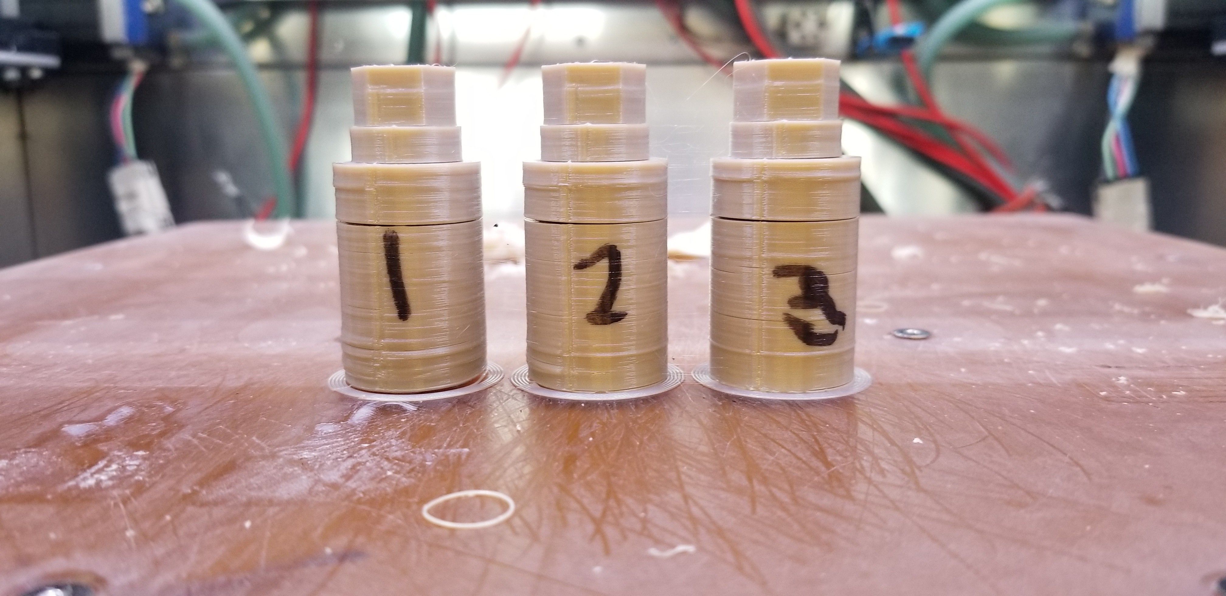
If the printed part shows brownish-translucent extrusions, this is an indication of incomplete crystallization that occurs when printing semi-crystalline. Therefore, the part can be annealed to induce crystallization.
As shown below, certain areas of the part have not been fully crystallized. Following a proper annealing schedule will optimize the performance of the printed part by completing the crystallization and improving interlayer welding. For more information, see the Post-Processing section.
Poor Interlayer Welding Strength
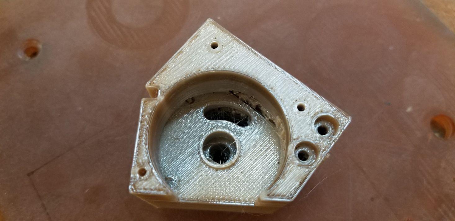
The fast crystallization rate of KetaSpire® PEEK when printing semi-crystalline may cause shrinkage or deformation; crystallization occurs after the extrusion is layered. The accumulation of stress due to crystallization starting from the first layer may cause the part to deform if the stress is large enough over time. Additionally, the interaction between each subsequent layer is diminished as crystals form at the surface of the layer, hindering proper intermixing of layers. As shown below, a KetaSpire® PEEK print experienced interlayer delamination and warping, mainly due to non-isometrical shrinking and poor interlayer welding.
Semi-crystalline printing requires a very high chamber temperature and high extrusion temperatures. Sufficient intermixing of the layers must occur before the material crystallizes; layers will not stick if crystallized too fast. For improved interlayer welding, avoid very high degrees of crystallization.
Crystallization During Amorphous Printing
If the extrusion and chamber temperatures are set too high, semi-crystalline instead of amorphous printing may occur. This problem can be seen as a mix of beige-opaque and brownish-translucent extrusions. The chamber temperature for amorphous printing should be set below its crystallization temperature, likely below its glass transition temperature. Print with a low chamber temperature and avoid extrusion temperatures near or at crystallization temperatures.
Stringing
Stringing may become an issue as KetaSpire® PEEK tends to stick a lot at its high extrusion temperatures. The nozzle will come into contact with extrusions if the Build Platform has not been properly probed and the Z offset is too small. Material may accumulate on the sides of the nozzle, potentially causing stringing during toolhead movements. Ensure that the bed has been properly probed with a sufficient Z offset distance as shown in the Z Calibration guide.
If stringing/oozing occurs even when Z-axis has been calibrated and the filament has been properly dried and fed from a low humidity environment, increase the Coasting Distance and/or the Wipe Distance before adjusting the Retraction Distance.