Inspect and Test Probe Assemblies
| Model | [ ] AON M2+ (CE) | [ ] AON M2+ (R-NZ) | [ ] AON M2+ | [•] AON-M2 2020 | [•] AON-M2 |
| Category | [•] Preventive | [ ] Corrective | |||
| Frequency | [ ] Daily | [ ] Weekly | [•] Monthly | [ ] Yearly | [ ] As Needed |
For instructions on how to inspect the two flex hinge probes found on the AON M2+ (CE), AON M2+ (R-NZ) and AON M2+, refer to the Inspect and Test Flex Hinge Probe Assemblies procedure.
Summary
The procedure that follows gives instructions on how to:
- Inspect the two probes.
- Tighten the two hot end assemblies, if necessary.
- Clean the two probes.
- Test the two probe assemblies.
Estimated time: 30 minutes
Tools
| Qty | Description | Specification |
|---|---|---|
| 1 | Hex Key | 3 mm |
| 1 | Brush, Wire | Brass, soft bristle |
| 1 | Cardboard Sheet | approximately 400 x 400 mm (16 x 16 in.) |
| A/R | Rags | Lint-free |
| A/R | Isopropyl Alcohol | 99% |
Parts Information
None required.
Personal Protective Equipment
| Qty | Description | Minimum Specification |
|---|---|---|
| 1 | Safety Eyewear | ANSI/ISEA Z87.1 |
| A/R | Nitrile Gloves | ISO 2859-1 or ASTM D6319 |
Prepare the Machine
Make sure that there are no prints on the build surface. Remove print(s) before the procedure that follows is started. Failure to do so can cause a collision and cause damage to the machine component(s).
- Home XYZ.
- Lower the Z-axis by 300 mm.
- Push the E-stop button.
- Wait until the build chamber, build platform and hot ends are at room temperature.
Inspect the Hot End Assemblies
Wait until all the machine components are at room temperature before you continue. Some machine components can be hot if the machine was recently used. Failure to do so can cause injuries.
Do the steps that follow to make sure that the hot end assembly is tight in the probe collar:
- Open the build chamber door.
- Put the cardboard sheet onto the center of the vacuum chuck.
- Manually move T0 to the center of the X-axis.
- Inspect the heater block assembly for damages and wear. Replace, if necessary. Refer to Replace Heater Block Assemblies
Reach out to our Customer Success team at help@aon3d.com for genuine AON3D replacement part(s) inquiries.
- Hold the bottom part of the hot end assembly and do the steps that follow:
- Lightly try to move the hot end assembly back and forth.
- Lightly try to move the hot end assembly right to left.
- Lightly try to turn the hot end assembly clockwise and counter-clockwise.
- Make sure that the hot end is tight in the probe collar.
- Do the steps that follow to inspect the T1 probe:
- Manually move T0 to the left-hand side of the X-axis.
- Manually move T1 to the center of the X-axis.
- Do steps 4 and 5, as necessary.
Tighten the Hot End Assemblies
- If the hot end assembly is not tight in the probe collar, refer to Inspect and Tighten One-Piece Probe Collar Set Screw
Clean the Hot End Assemblies
Do not use compressed air to clean the probe assemblies. The use of compressed air can cause damages to machine component(s).
- Use the wire brush to remove unwanted material from between the probe collar and the probe adapter plate.
- Use the wire brush to remove unwanted material from the hot end assembly.
- Use the isopropyl alcohol and lint-free rag(s) to clean solvents from the hot end assembly.
- Let the hot end assembly dry for two minutes.
- Use your hand to manually push the hot end assembly up to compress the compression springs, and then release. Do this three times.
- Make sure that the hot end assembly moves up and down freely.
- Do steps 1 to 5 for the adjacent toolhead, if necessary.
- Remove the cardboard sheet from the build plate.
Test and Return to Service
- Make sure that you remove all the tools from the build chamber.
- Clean the build platform and build chamber, if necessary. Refer to the Clean Build Platform and Build Chamber procedure.
- Release the E-stop button.
- Home XYZ.
- Lower the Z-axis by 300 mm.
- Do the steps that follow to test the probe assembly:
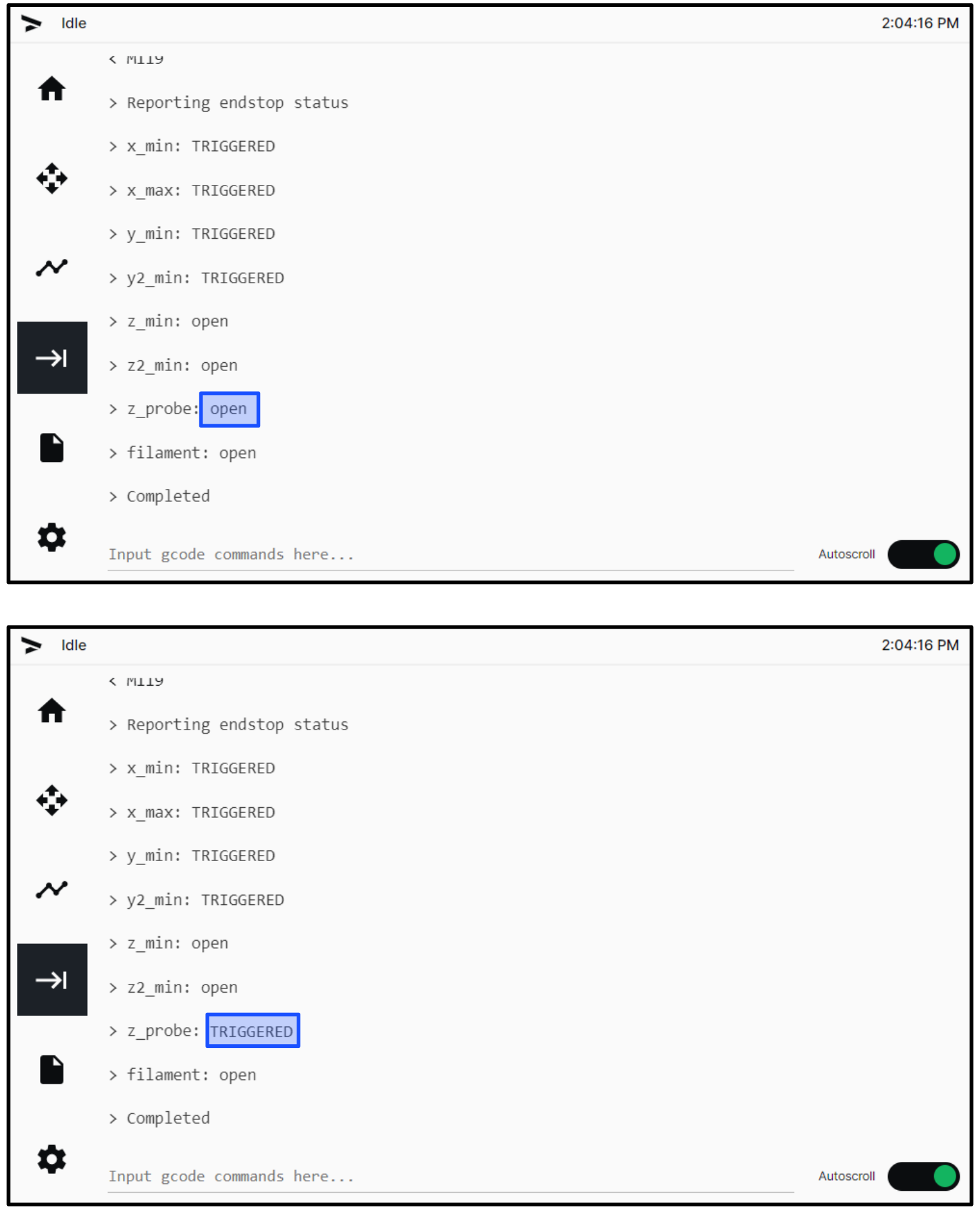
- On the GUI, select Terminal and input M119. Make sure that z_probe T0: open and z_probe T1: open is shown on the GUI.
- Manually compress the T0 probe and input M119. Make sure that z_probe T0: triggered is shown on the GUI.
- Release the T0 probe and input M119. Make sure that z_probe T0: open is shown on the GUI.
- Do steps 6a to 6c for the adjacent probe.
- Close the build chamber door.
- Home XYZ.