Inspect and Test Flex Hinge Probe Assemblies
| Model | [•] AON M2+ (CE) | [•] AON M2+ (R-NZ) | [•] AON M2+ | [ ] AON-M2 2020 | [ ] AON-M2 |
| Category | [•] Preventive | [ ] Corrective | |||
| Frequency | [ ] Daily | [ ] Weekly | [•] Monthly | [ ] Yearly | [ ] As Needed |
For instructions on how to inspect the two probes found on the AON-M2 and the AON-M2 2020, refer to the Inspect and Test Probes procedure.
Summary
The procedure that follows gives instructions on how to:
- Inspect the two flex hinge probes.
- Clean the two flex hinge probes.
- Tighten the two hot end assemblies, if necessary.
- Clean the two hot end assemblies.
- Test the two flex hinge probe assemblies.
Estimated time: 30 minutes
Do not disassemble and/or make adjustments to the AON3D Flex Hinge Probes. The AON3D Flex Hinge Probe is a calibrated instrument that can only be calibrated by AON3D technicians.
Tools
| Qty | Description | Specification |
|---|---|---|
| 1 | Hex Key | 3 mm |
| 1 | Brush, Wire | Brass, soft bristle |
| 1 | Cardboard Sheet | approximately 400 x 400 mm (16 x 16 in.) |
| A/R | Rags | Lint-free |
| A/R | Isopropyl Alcohol | 99% |
Parts Information
None required.
Personal Protective Equipment
| Qty | Description | Minimum Specification |
|---|---|---|
| 1 | Safety Eyewear | ANSI/ISEA Z87.1 |
| A/R | Nitrile Gloves | ISO 2859-1 or ASTM D6319 |
Prepare the Machine
Make sure that there are no prints on the build surface. Remove print(s) before the procedure that follows is started. Failure to do so can cause a collision and cause damage to the machine component(s).
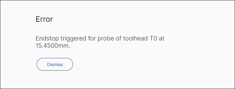
The amount of 20 mm of filament must be retracted from the hot end assembly(ies) before the machine is powered OFF. Failure to retract the filament can cause the filament to harden in the hot end(s) and can cause damage to the AON M2+ flex hinge probe assembly(ies), and/or, can signal the GUI to notify the user with an error message.
Use the GUI to retract the filament as follows:
- Select Temperatures (Temp), and input the toolhead(s) target temperature necessary.
- Let the toolhead(s) get to the target print temperature(s).
- Select Control > Motion.
- Under Tool Select, select
T0orT1(Left ToolorRight Tool). - Under the Extrusion Distance (mm), select
10. - Under the Extrusion Speed (mm/sec), select
3. - Select the Retract button two times to retract 20 mm of filament.
- Do steps 4 and 7 for the adjacent toolhead, if necessary.
- Lower the Z-axis by 300 mm.
- Open the build chamber door.
- Push the E-stop button.
- Wait until the build chamber, build platform and hot ends are at room temperature.
Clean the Flex Hinge Probes
Do not remove, tighten and/or adjust the brass precision screw. The AON3D Flex Hinge Probe is a calibrated instrument that can only be calibrated by AON3D technicians.
- Manually put the selected toolhead to the center of the X-axis.
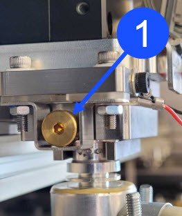
- Use the isopropyl alcohol and lint-free rag(s) to clean solvents from the brass precision screw (1) found on the left side of the flex hinge probe assembly.
- Let the brass precision screw (1) dry for two minutes.
- Make sure that the brass precision screw (1) is clean. Do steps 2 and 3 as necessary.
- Do steps 1 to 4 for the adjacent flex hinge probe assembly, if necessary.
Inspect the Hot End Assemblies
Wait until all the machine components are at room temperature before you continue. Some machine components can be hot if the machine was recently used. Failure to do so can cause injuries.
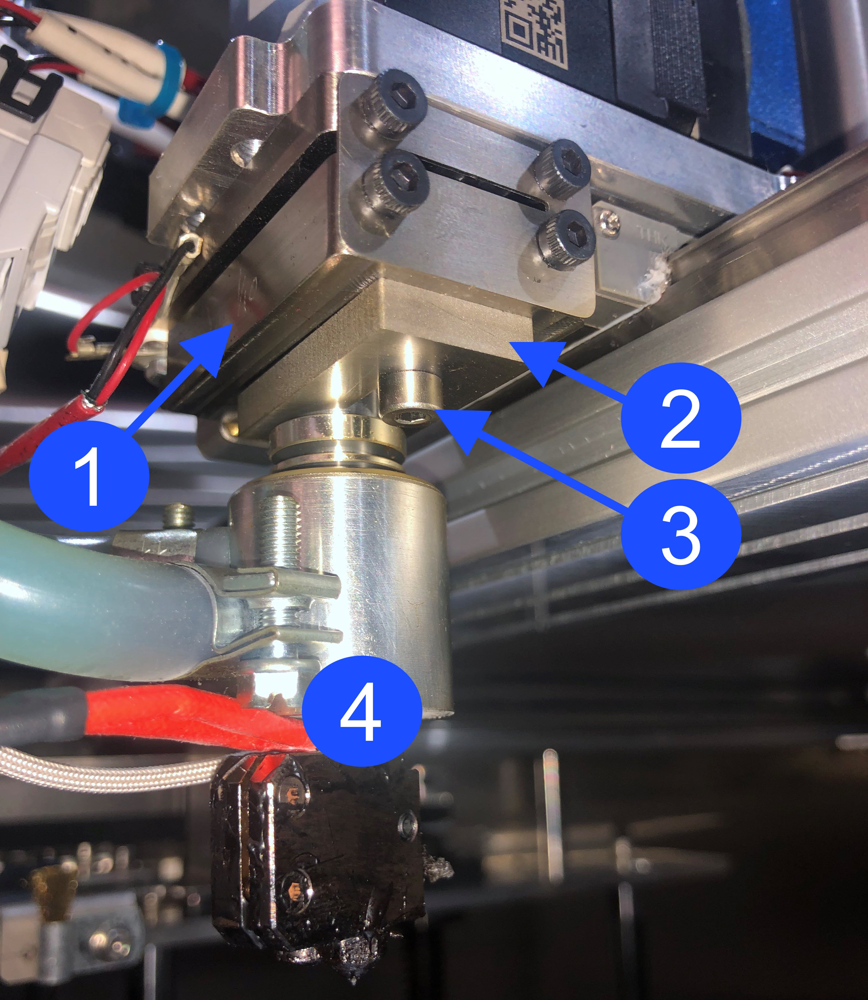
Do the steps that follow to make sure that the T0 hot end assembly (4) is tight in the bottom hinge flex plate (1):
- Put the cardboard sheet onto the center of the vacuum chuck.
- Manually move T0 to the center of the X-axis.
- Inspect the heater block assembly for damages and wear. Replace, if necessary. Refer to Replace Heater Block Assembly
Reach out to our Customer Success team at help@aon3d.com for genuine AON3D replacement part(s) inquiries.
- Hold the bottom part of the hot end assembly (4) and do the steps that follow:
- Lightly try to move the hot end assembly (4) back and forth.
- Lightly try to move the hot end assembly (4) right to left.
- Lightly try to turn the hot end assembly (4) clockwise and counter-clockwise.
- Make sure that the hot end assembly (4) is tight in the bottom hinge flex plate (1).
- Inspect the flex probe hot end clip (2). Make sure that the 3 mm screw (3) is tight.
- To inspect the T1 hot end assembly, do the steps that follow:
- Manually move T0 to the left-hand side of the X-axis.
- Manually move T1 to the center of the X-axis.
- Do steps 3 and 4.
Tighten the Hot End Assemblies
If the hot end is not tight on the bottom hinge flex plate, and/or the flex probe hot end clip is loose, do the steps that follow:
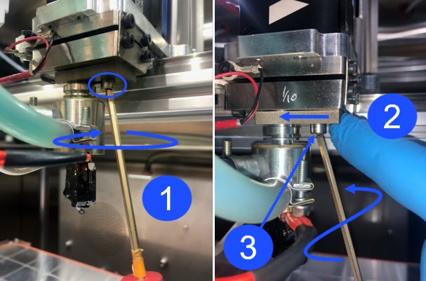
- Use the 3 mm hex key to loosen the screw (3) that holds the flex probe hot end clip onto the bottom hinge flex plate. Do not remove the screw.
Do not remove the screw that holds the flex probe hot end clip. The removal of the screw will let the flex probe fall out of the bottom hinge plate and can cause damages to the machine component(s).
- Use your finger to apply light pressure on the flex probe hot end clip towards the left of the machine. Make sure that the flex probe hot end clip is correctly installed on the hot end.
- Use the 3 mm hex key to tighten the screw. Do not tighten too much.
- Make sure that the hot end is tight in the bottom hinge plate. Hold the bottom part of the hot end and do the steps that follow:
- Lightly try to move the hot end assembly back and forth.
- Lightly try to move the hot end assembly right to left.
- Lightly try to turn the hot end assembly clockwise and counter-clockwise.
- Make sure that the hot end assembly is tight in the bottom hinge plate.
- Do steps 1 to 4 for the adjacent toolhead, if necessary.
Clean the Hot End Assemblies
Do not use compressed air to clean the AON3D flex hinge probe assemblies. The use of compressed air can cause damage to machine component(s).
Do the steps that follow to clean the hot end assemblies:
- Use the wire brush to remove unwanted material from the hot end assembly.
- Use the isopropyl alcohol and lint-free rag(s) to clean solvents from the hot end assembly.
- Let the hot end assembly dry for two minutes.
- Do steps 1 to 3 for the adjacent toolhead, if necessary.
- Remove the cardboard sheet from the vacuum chuck.
Test and Return to Service
- Make sure that you remove all the tools from the build chamber.
- Clean the build platform and build chamber, if necessary. Refer to the Clean Build Platform and Build Chamber procedure.
- Close the build chamber door.
- Release the E-stop button.
- Home XYZ.
- Open the build chamber door.
- Do the steps that follow to test the flex hinge probe assembly:
- For the Klipper-based firmware:
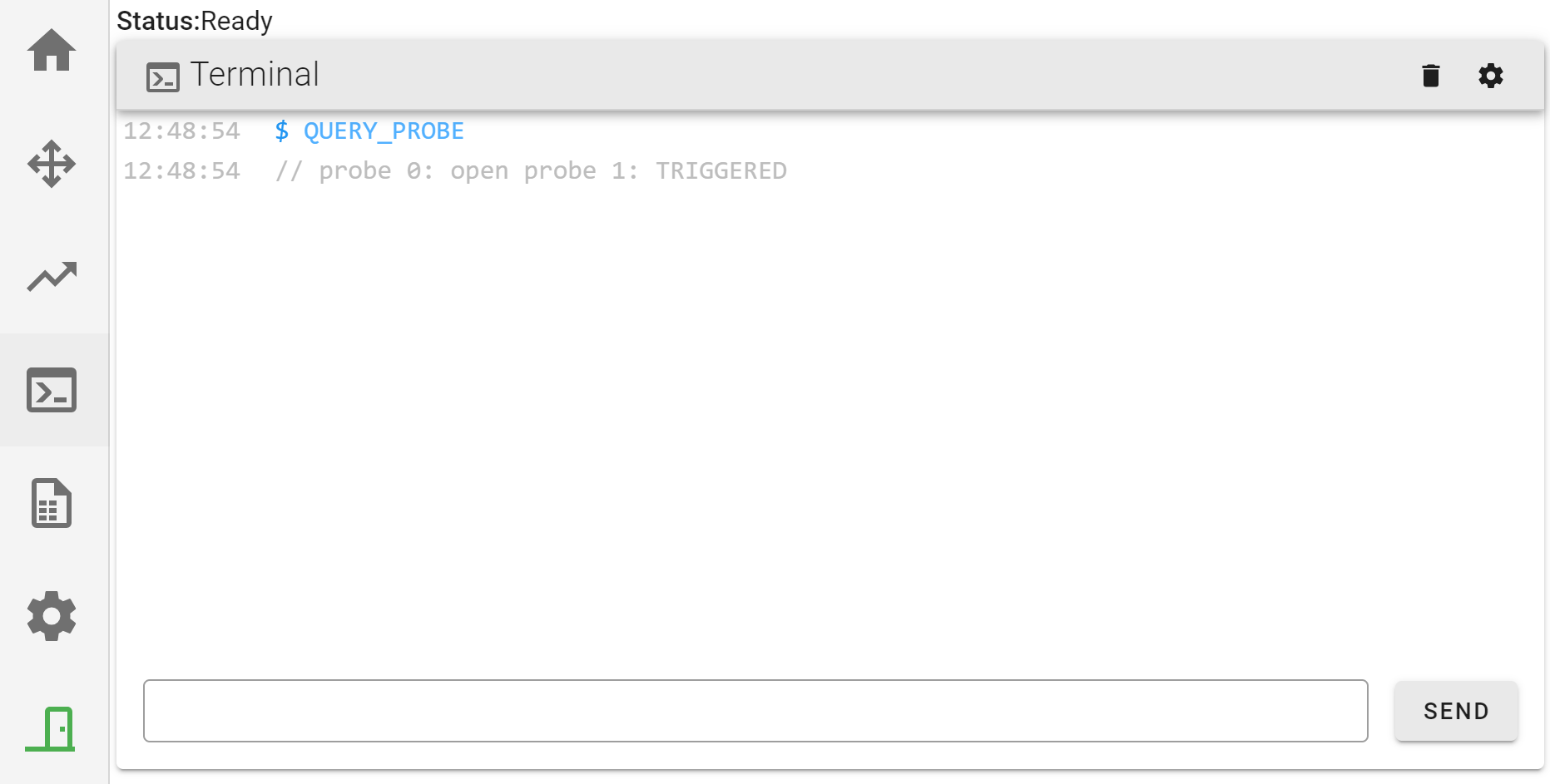
- On the GUI, select Terminal and input
QUERY_PROBE. Make sure thatprobe 0: openandprobe 1: openis shown on the GUI. - Manually compress the T0 flex hinge probe and input
QUERY_PROBE. Make sure thatprobe 0: TRIGGEREDis shown on the GUI. - Release the T0 flex hinge probe and input
QUERY_PROBE. Make sure thatprobe 0: openis shown on the GUI. - Do steps 7a.i to 7a.iii for the adjacent flex hinge probe.
- On the GUI, select Terminal and input
- For the Marlin-based firmware:
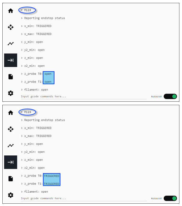
- On the GUI, select Terminal and input
M119. Make sure thatz_probe T0: openandz_probe T1: openis shown on the GUI. - Manually compress the T0 flex hinge probe and input
M119. Make sure thatz_probe T0: TRIGGEREDis shown on the GUI. - Release the T0 flex hinge probe and input
M119. Make sure thatz_probe T0: openis shown on the GUI. - Do steps 7b.i to 7b.iii for the adjacent flex hinge probe.
- On the GUI, select Terminal and input
- For the Klipper-based firmware:
- Close the build chamber door.
- Home XYZ.
- Probe the build surface. Refer to Auto Bed Leveling.
- Extrude and purge filament. Refer to Replace Filament.