Extruder Tab
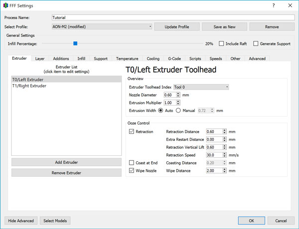
The Extruder tab contains hot end configuration settings and retraction behavior.
Extruder List
This box lists all the extruders available on your printer. For the AON-M2, you will have 2 labeled “T0/Left Extruder” and “T1/Right Extruder” corresponding to the physical left- and right-hand side toolheads when facing the printer from the front. Note that this toolhead convention will be consistent across all of AON3D’s documentation.
By highlighting one of the two extruders, you are able to change settings specific to that toolhead on the right hand side of the screen.
This setting will not need modification once set.
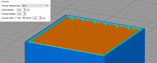
Extruder Toolhead Index
This setting allows Simplify3D® to generate G-code properly for the firmware.
Ensure that when “T0/Left Extruder” is selected, the toolhead index is set to “Tool 0”, and when “T1/Right Extruder” is selected, the toolhead index is set to “Tool 1”.
This setting will not need modification once set.
Nozzle Diameter
The nozzle diameter setting is used by Simplify3D® to calculate the Auto Extrusion setting below, and should generally correspond to the size of the physical nozzle you have installed for that toolhead. By default, the AON-M2 ships with 0.6mm nozzles installed on both toolheads.
When you swap out the nozzle on either of the toolheads, update this setting accordingly.
The AON-M2 has the following nozzle sizes available:
- 0.25mm
- 0.30mm
- 0.40mm
- 0.60mm
- 0.80mm
- 1.00mm
- 1.20mm
Custom nozzle sizes may be available on request.
Technically, the nozzle diameter in and of itself has no bearing on the actual toolpath generation. Its main purpose is to facilitate the automatic calculation of the Extrusion Width by multiplying the nozzle diameter by 1.2. You can see this for yourself by slicing a test file with two different nozzle diameters, but the Extrusion Width manually set to a constant value. The G-code preview will show no difference in the toolpaths generated.
Extrusion Multiplier
Simplify3D® calculates the volume of material to extrude along a toolpath by taking settings such as extrusion width and layer height into account. The Extrusion Multiplier applies a linear scaling factor to the volumetric extrusion rate.
Different materials have different viscosities which results in varying levels of back-pressure in the hot end’s melt zone which then causes different rates of ‘slippage’ in the toothed extruder gear that drives the filament into the hot end. By adjusting the Extrusion Multiplier, one can easily compensate for this phenomenon without having to recalibrate the extruder feedrate entirely.
The AON-M2 is calibrated such that with a multplier of 1.00, our brand of ABS at 250°C extrudes exactly 100mm of filament as commanded. Lower viscosity materials such as polycarbonate would overextrude with a multiplier of 1.00 so should be adjusted downwards, while higher viscosity materials such as Nylon would underextrude with a multiplier of 1.00 so should be adjusted upwards.
Extrusion Width
The Extrusion Width actually determines the width of the extrudate bead that comes out of the nozzle during printing. When “Auto” is selected, Simplify3D® reverts to the default of using 1.2 times the Nozzle Diameter, but it can be overridden manually to any value you like.
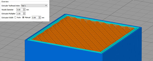
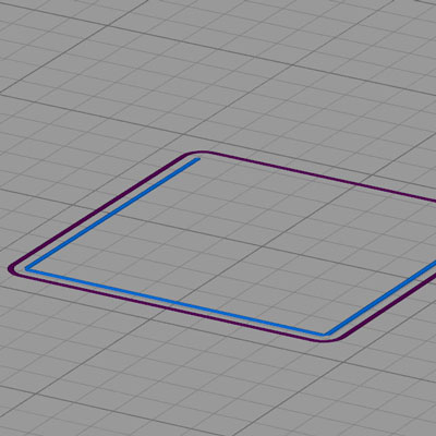
For example, one could set two arbitrary Nozzle Diameters but if the same Extrusion Width is set for both, the generated toolpath and flow rate out of the nozzle will be identical.
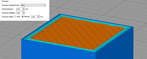
In contrast, the same Nozzle Diameter with different Extrusion Widths will change the toolpath and flowrate.
In general, the auto setting works perfectly well. The most optimal Extrusion Width setting is a function of a material’s flow characteristics, extrusion rate, temperature, part geometry, nozzle size, and often overlooked - the geometry of the nozzle tip. Extrusion Width selection is particularly important when thin walls or small geometries are involved.
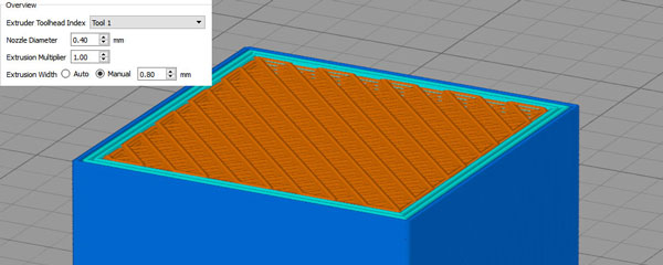
Consider a part with a thin wall. In the example below, the wall thickness of the model is 0.8mm. If we were to slice the model with an Extrusion Width of 0.4mm, two passes will be sufficient to precisely create the geometry.
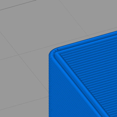
If we slice the model with an Extrusion Width of 0.6mm, the toolpath still makes two passes, but the extrusion will overlap resulting in poor surface finish quality.
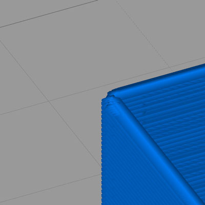
If we slice the model with an Extrusion Width of 0.7mm, only one pass is generated by the slicer resulting in an undersized wall thickness.

If we slice the model with an Extrusion width of 0.9mm, the geometry is ignored by the slicer altogether.
However, Simplify3D® also has a separate feature to counteract this behavior in the Advanced tab under Thin Wall Behavior.
In general, a larger Extrusion Width results in greater part strength but at the expense of detail resolution and occasionally tolerance depending on the complexity of the surface geometry/topology. A smaller Extrusion Width yields higher detail resolution, and improved surface finish, but at the expense of significantly longer print times and lower strength.
It should be noted that the nozzle size selection should still match the desired Extrusion Width ie. trying to print 0.8mm extrusion width with a 0.3mm nozzle will not only result in severe underextrusion, the print quality and layer bonding strength will also be poor. Avoid choosing an Extrusion Width greater than 1.75 times the nozzle diameter (especially with more viscous materials), and do not choose an Extrusion Width less than the nozzle diameter.
Pointed nozzle tip geometries will result in a poorer surface finish if the Extrusion Width is much greater than the nozzle diameter, while “flat” nozzle tip geometries are more forgiving of a higher range due to the bead-forming effect the flat surface has when the material flows out of the nozzle.
Ooze Control
Retraction Distance
During travel moves (movement of the toolhead from one point to another without extruding material), the extruder will pull filament back from the hot end and then return to its original position at the start of the next extrusion move to reduce material leakage from the nozzle tip which can create a messy print (known as “oozing” or “stringing”). This behavior is referred to as Retraction.
Retraction Distance defines how far the filament is pulled back during a retraction movement. If this value is too small, the pressure reduction will not be sufficient resulting in stringing. If this value is too large, the retraction movement will take too long allowing the material to leak in place and create a blob at the location where retraction is occurring (however, the Coast at End and Wipe Nozzle settings can compensate for this). In general, a retraction value between 0.5mm to 1.0mm is sufficient for most materials, and between 1.0mm and 2.0mm for naturally “stringy” materials such as Nylon.
For parts requiring many consecutive retraction movements in a row, a high Retraction Distance can also result in print failure due to a) insufficient priming of the extruder and b) the extruder feed gear wearing down the filament and losing grip. In these cases, reducing the Retraction Distance and increasing the Coasting Distance is recommended.
Extra Restart Distance
Extra Restart Distance can be a positive or negative value and can compensate for one of two situations.
-
Short or consecutive rapid travel moves where the melt zone pressure drops but actual ooze does not occur - the hot end will extrude extra material at the start of the next extrusion move resulting in a blob.
A negative Extra Restart Distance will compensate for this.
-
Long travel moves where there is sufficient time for material to ooze - the hot end will not be fully primed at the start of the next travel move resulting in a gap where no material comes out.
A positive Extra Restart Distance will compensate for this.
Unfortunately, the slicer cannot selectively apply different retraction strategies by automatically detecting the type of travel move. Depending on your part geometry, a balance between Retraction Distance and Extra Restart Distance must be found. Typical values will be +/-0.1 to 0.2mm.
Retraction Vertical Lift
Retraction Vertical Lift is the amount the Z axis moves up/down during a retraction/travel move, and is recommended to be 2-2.5 times the value of your selected Layer Height.
Retraction Speed
Retraction Speed is how fast the extruder moves filament for a retraction move and should generally be set to the maximum feed rate of the extruder, which is 30mm/s.
Coasting Distance
Coast at End and Wipe Nozzle are two complementary approaches to “wipe” the nozzle at the end of an extrusion move and before/during a retraction move to combat not only stringing but the quality of the surface seam which occurs at the end of an extrusion movement. The correct settings will minimize visual print artefacts.
Coast at End stops extruding filament before the end of the extrusion movement by the selected distance. A value that is too high here will create a gap in the surface of the print, while a value that is too low will result in a blob at the seam. Typical values will be under 1mm.
Wipe Distance
Wipe Nozzle extends the toolpath movement beyond the end of the extrusion path by the selected distance without additional extrusion, effectively wiping off any ooze that occurs during retraction. A value too low will be ineffective at minimizing ooze/surface blobbing, while a value too high creates a larger seam artefact. Typical values are between 1mm and 3mm.
The ideal values for Coast at End and Wipe Nozzle are defined mostly by the Retraction Distance (as the intention is to compensate for any negative effects of retraction), and may be used in conjunction, one over the other, or none at all. For example, a material like Nylon is particularly susceptible to oozing and will call for a larger Retraction Distance, which means Coast at End/Wipe Nozzle is recommended as a compensating measure. A material like ABS may print just fine without Coast at End or Wipe Nozzle.