Replace Probe Assemblies
| Model | [ ] AON M2+ (CE) | [ ] AON M2+ (R-NZ) | [ ] AON M2+ | [•] AON-M2 2020 | [•] AON-M2 |
| Category | [ ] Preventive | [•] Corrective |
Summary
The procedure that follows gives the instructions on how to replace the AON3D probe assemblies found on the AON-M2 and AON-M2 2020 machines.
Estimated time: 45 minutes
Tools
| Qty | Description | Specification |
|---|---|---|
| 1 | Hex Key | 2.5 mm |
| 1 | Hex Key | 2 mm |
| 1 | Brush, Grease Applicator | N/A |
| A/R | Rags | Lint-free |
| A/R | Isopropyl Alcohol | 99% |
Parts Information
| Qty | Part Number | Description |
|---|---|---|
| 1 | M2-SUB-PROBE | M2 Probe sub-assembly |
| A/R | 12542D37 | White Loctite® Grease LB8042 1.5oz |
Reach out to our Customer Success team at help@aon3d.com for genuine AON3D replacement part(s).
Personal Protective Equipment
| Qty | Description | Minimum Specification |
|---|---|---|
| 1 | Safety Eyewear | ANSI/ISEA Z87.1 |
| 1 | Safety Footwear | N/A |
| A/R | Nitrile Gloves | ISO 2859-1 or ASTM D6319 |
Prepare the Machine
Make sure that there are no prints on the build surface. Remove print(s) before the procedure that follows is started. Failure to do so can cause a collision and cause damage to the machine component(s).
- Unload the filament. Refer to Replace Filament.
- Home XYZ.
- Lower the Z-axis by 100 mm.
- Open the build chamber door.
- Press the E-stop button.
- Turn the power OFF with the ON/OFF switch found on the rear panel of the machine.
- Disconnect the main power cord from the receptacle.
- Wait until the build chamber, build platform and hot ends are at room temperature.
Wait until all the machine components are at room temperature before you continue. Some machine components can be hot if the machine was recently used. Failure to do so can cause injuries.
- Remove the heater block assembly. Refer to Replace Heater Block Assemblies.
Remove the Water Cooled Heat Sink
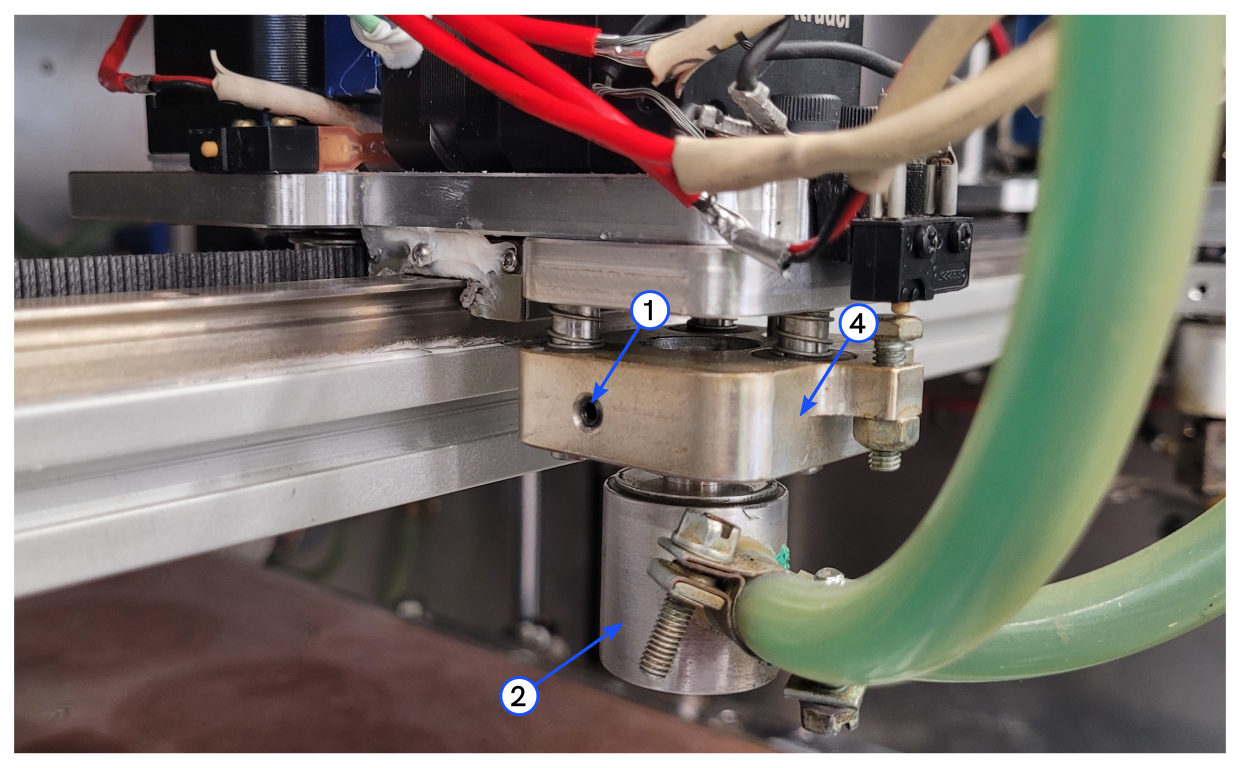
- Use the 2 mm hex key to loosen the set screw (1).
- Remove out the water cooled heat sink (2) from the one-piece collar (4). Do not disconnect the coolant tubes that are attached to the water cooled heat sink (2).
- Put the water cooled heat sink (2) behind the X-axis gantry, away from the probe assembly.
Remove the Probe Assembly
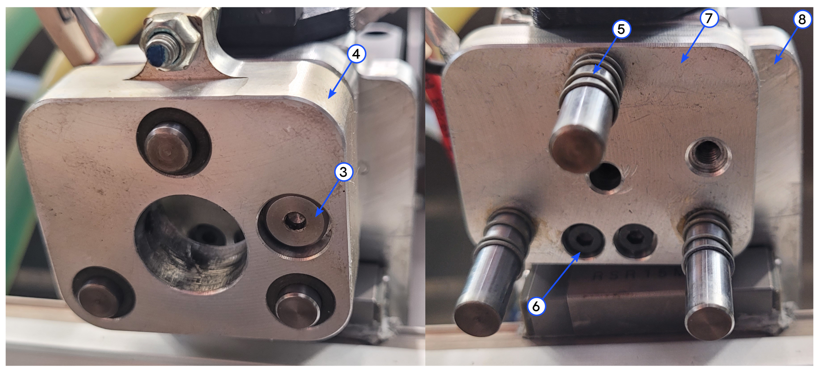
- Use the 2.5 mm hex key to remove the shoulder screw (3). Discard the shoulder screw.
- Remove the one-piece collar (4) and the three compression springs (5). Discard the one-piece collar and the three compression springs.
- Use the 2.5 mm hex key to remove the two screws (6) and the toolhead adapter plate (7). Discard the toolhead adapter plate.
- Use a lint-free rag and isopropyl alcohol to clean the bottom surface of the toolhead carriage plate (8).
- Let the clean surface dry for two minutes.
Prepare the New Probe Assembly
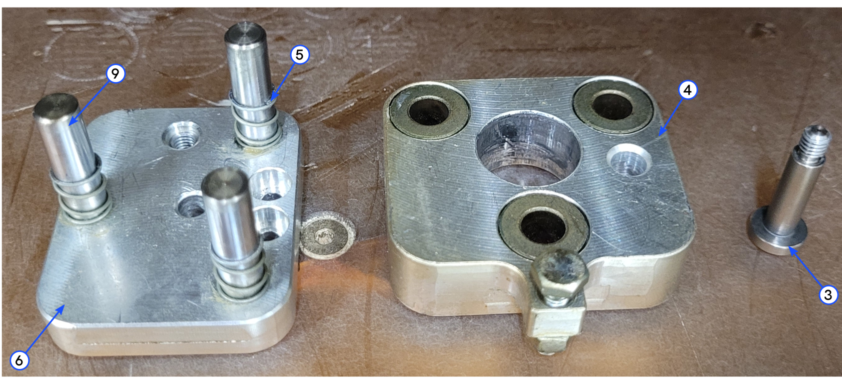
- Use the 2.5 mm hex key to remove the new shoulder screw (3).
- Remove the new one-piece collar (4). Set aside.
- Remove the three new compression springs (5). Set aside.
- Use a lint-free rag and isopropyl alcohol to clean the top and bottom surfaces of the new probe adapter plate (7).
- Let the clean surfaces dry for two minutes.
- Use the grease applicator brush to apply a small quantity of white lithium grease onto the three probe adapter plate posts (9).
- Install one new compression spring (5) onto the three probe adapter plate posts (9).
Install the New Probe Assembly
- Put the new probe adapter plate (7) in position onto the toolhead carriage plate (8). The probe adapter plate plate (7) must be square with the toolhead carriage plate (8).
- Use the 2.5 mm hex key to install the two screws (6) through the probe adapter plate (7), and into the toolhead carriage plate (8). Make sure that the two screws are tight.
Make sure that the heads of the two screw are seated flush (or lower) than the surface of the probe adapter plate. Failure to do so can cause damage to the machine component(s).
- Install the new one-piece collar (4) onto probe adapter plate (7). Make sure that the three compression springs (5) are installed on the three probe adapter plate posts (9).
- Use the 2.5 mm hex key to install the new shoulder screw (3) through the one-piece collar (4) and into the probe adapter plate (7). Make sure that the shoulder screw is tight.
Install the Water Cooled Heat Sink
- Use a lint-free rag and isopropyl alcohol to clean the top of the water cooled heat sink (2).
- Let the clean surface dry for two minutes.
- Use the 2 mm hex key to loosen the set screw (1).
- Install the water cooled heat sink (2) into the one-piece collar (4).
- Make sure that the top of the water cooled heat sink (2) is flush with the one-piece collar (4).
- Use the 2 mm hex key to tighten the set screw (1).
Make sure that there is no interference between the two water cooled heat sink coolant tube clamps and the movement of the probe assembly. Failure to do so can cause damage to the machine component(s).
- Adjust the probe microswitch. Refer to Inspect, Adjust and Tighten Probe Microswitches.
Test and Return to Service
- Install the heater block assembly. Refer to Replace Heater Block Assemblies.
- Make sure that you remove all the tools from the build chamber.
- Close the build chamber door.
- Connect the main power cord to the receptacle.
- Turn the power ON at the ON/OFF switch found on the rear panel of the machine.
- Release the E-stop button.
- Home XYZ.
- Make sure that the probe microswitches operate correctly. Refer to the Test Microswitches procedure.
- Preheat the build chamber components. Refer to Preheat Build Chamber Components.
- Probe the print surface. Refer to Auto Bed Leveling.
- Load the filament. Refer to Replace Filament.