Inspect, Adjust and Tighten Probe Microswitches
| Model | [ ] AON M2+ (CE) | [ ] AON M2+ (R-NZ) | [ ] AON M2+ | [•] AON-M2 2020 | [•] AON-M2 |
| Category | [•] Preventive | [ ] Corrective | |||
| Frequency | [•] Daily | [ ] Weekly | [ ] Monthly | [ ] Yearly | [ ] As Needed |
For instructions on how to inspect and tighten the XYZ-axes microswitches found on the AON-M2 and the AON-M2 2020, refer to the Inspect and Tighten XYZ-Axes Microswitches procedure.
Summary
The procedure that follows gives instructions on how to inspect, adjust, and tighten the two probe microswitches.
Estimated time: 30 minutes
Probe microswitches in good condition prevent:
- Incorrect probe reference points.
- Unsatisfactory print layer quality.
Tools
| Qty | Description | Specification |
|---|---|---|
| 1 | Hex Key | 4 mm |
| 1 | Hex Key | 1.5 mm |
| 2 | Wrench | 7 mm, open |
| 1 | Brush, Wire | Clean, soft bristle |
| 1 | Feeler Gauge | 0.003 inch (0.076 mm) thick, blade-type |
Parts Information
None required.
Personal Protective Equipment
| Qty | Description | Minimum Specification |
|---|---|---|
| 1 | Safety Eyewear | ANSI/ISEA Z87.1 |
| A/R | Nitrile Gloves | ISO 2859-1 or ASTM D6319 |
Prepare the Machine
Make sure that there are no prints on the build surface. Remove print(s) before the procedure that follows is started. Failure to do so can cause a collision and cause damage to the machine component(s).
- Home XYZ.
- Lower the Z-axis by 300 mm.
- Push the E-stop button.
- Open the build chamber door.
- Wait until the build chamber, build platform and hot ends are at room temperature.
Inspect and Tighten Probe Microswitches
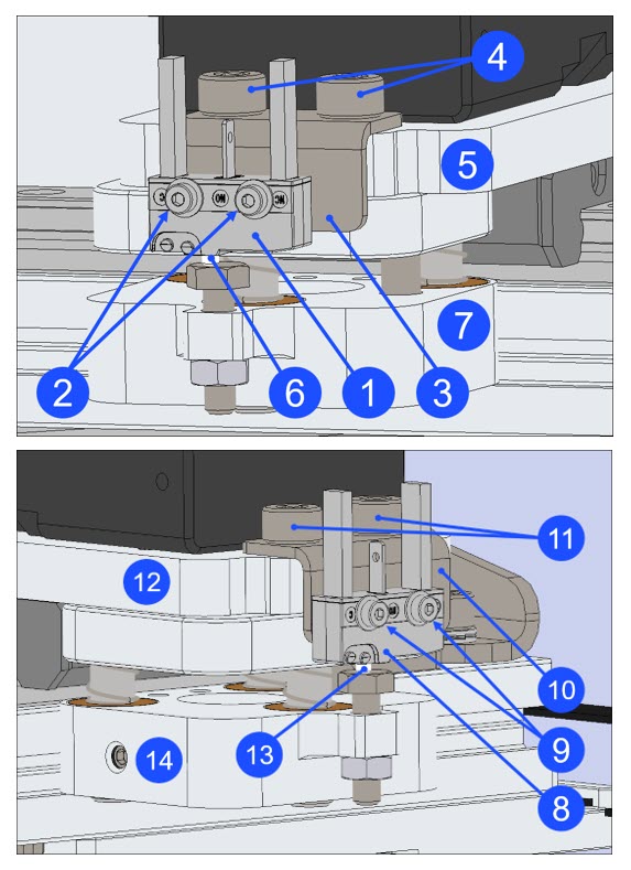
Left Microswitch
- Inspect the left probe microswitch (1) found on T0.
- Make sure that the probe microswitch (1) has no cracks and/or defects. Replace if necessary. Refer to Replace Probe Microswitches.
- Make sure that the two screws (4), found on the probe microswitch bracket (3), are tight.
- Use the 4 mm hex key to lightly tighten the two screws (4), if necessary. Do not tighten too much.
- Make sure that the two probe microswitch screws (2) are tight.
- Use the 1.5 mm hex key to lightly tighten the two probe microswitch screws (2), if necessary. Do not tighten too much.
- Manually compress the probe collar (7), and release. Do this step three times.
- Listen for a click when the microswitch actuator (6) is compressed, and a click when the microswitch actuator (6) is released.
- If the microswitch actuator (6) does not function correctly, use the 1.5 mm hex key to loosen the two screws (2), and lightly tighten the two screws again. Do not tighten too much.
- Make sure that the microswitch actuator (6) functions correctly. Test the Z-axis probe microswitch (1), if necessary. Refer to Test Microswitches.
- Replace the probe microswitch (1), if necessary. Refer to Replace Probe Microswitches.
- Probe the print surface. Refer to Auto Bed Leveling.
Right Microswitch
- Inspect the right probe microswitch (8) found on T1.
- Make sure that the probe microswitch (8) has no cracks and/or defects. Replace if necessary. Refer to Replace Probe Microswitches.
- Make sure that the two probe microswitch screws (11), found on the probe microswitch bracket (10), are tight.
- Use the 4 mm hex key to lightly tighten the two screws (11), if necessary. Do not tighten too much.
- Make sure that the two probe microswitch screws (9) are tight.
- Use the 1.5 mm hex key to lightly tighten the two screws (9), if necessary. Do not tighten too much.
- Manually compress the probe collar (14), and release. Do this step three times.
- Listen for a click when the microswitch actuator (13) is compressed, and a click when the microswitch actuator (13) is released.
- If the microswitch actuator (13) does not function correctly, use the 1.5 mm hex key to loosen the two screws (9), and lightly tighten the two screws again. Do not tighten too much.
- Make sure that the microswitch actuator (13) functions correctly. Test the Z-axis probe microswitch (8), if necessary. Refer to Test Microswitches.
- Replace the probe microswitch (8), if necessary. Refer to Replace Probe Microswitches.
- Probe the print surface. Refer to Auto Bed Leveling.
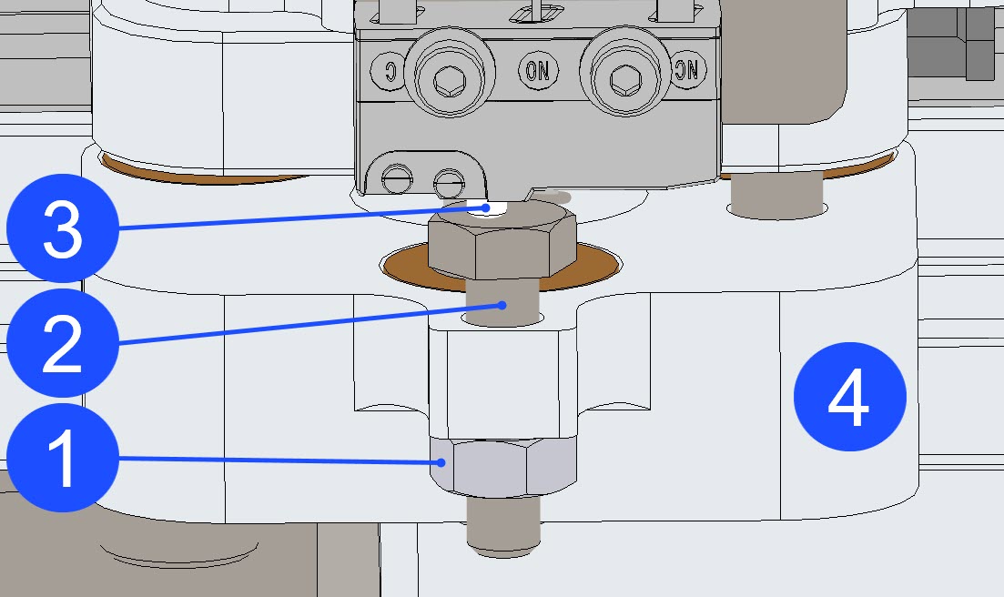
Adjust the Probe Microswitches
- Manually put the selected toolhead to the center of the X-axis linear rail.
- Use the 7 mm wrench to loosen the 4 mm nut (1).
- Make sure that the 4 mm nut (1) is loose.
- Do not remove the 4 mm nut (1) from the 4 mm bolt (2).
- Use the 7 mm wrench to loosen the 4 mm bolt (2) approximately three turns clockwise.
- Make sure that head of the 4 mm bolt (2) is clean. Use the wire brush to clean the head of the 4 mm bolt (2) that activates the probe microswitch actuator (3), if necessary.
- Manually compress the one-piece collar (4), then release. Do this step three times.
- Make sure that the one-piece collar (4) operates correctly and without restrictions.
- Use the 7 mm wrench to carefully raise the head of the 4 mm bolt (2) approximately 1 mm away from the Z-axis probe microswitch actuator (3). Do not let the head of the 4 mm bolt (2) touch the Z-axis probe microswitch actuator (3).
- Put the 0.003 inch (0.076 mm) feeler gauge between the head of the 4 mm bolt (2) and the Z-axis probe microswitch actuator (3).
- Hold the 0.003 inch (0.076 mm) feeler gauge in this position.
- With your other hand, use the 7 mm wrench to carefully tighten the 4 mm bolt (2) towards the Z-axis probe microswitch actuator (3). Do not let the head of the 4 mm bolt (2) compress the Z-axis probe microswitch actuator (3).
- Carefully move the 0.003 inch (0.076 mm) feeler gauge in and out as the 4 mm bolt (2) is it gets closer to the Z-axis probe microswitch actuator (3).
- When a restriction is felt between the head of the 4 mm bolt (2) and the Z-axis probe microswitch actuator (3), do not tighten the 4 mm bolt (2) more. Do not compress the Z-axis probe microswitch actuator (3).
- Remove the 0.003 inch (0.076 mm) feeler gauge. Do not remove the 7 mm wrench that holds the 4 mm bolt (2) at this point in time.
- Use the second 7 mm wrench to carefully tighten the 4 mm nut (1) against the one-piece collar (4). When the 4 mm nut (1) is tight, remove the two 7 mm wrenches.
- Put the 0.003 inch (0.076 mm) feeler gauge between the head of the 4 mm bolt (2) and the Z-axis probe microswitch actuator (3).
- There must be a small restriction between the Z-axis probe microswitch actuator (3) and the head of the 4 mm bolt (2). Make sure that the Z-axis probe microswitch actuator (3) does not compress when the 0.003 inch (0.076 mm) feeler gauge is put between the Z-axis probe microswitch actuator (3) and the head of the 4 mm bolt (2).
- If the clearance between the head of the 4 mm bolt (2) and the Z-axis probe microswitch actuator (3) is not satisfactory, do the steps that follow:
- Loosen the 4 mm nut (1).
- Loosen the 4 mm bolt (2).
- Do steps 7 to 12 as necessary.
- Calibrate the Z-axis. Refer to the Calibrate the Z-Axis procedure.
- Do steps 1 to 13 for the adjacent toolhead, if necessary.
Test and Return to Service
- Make sure that you remove all the tools from the build chamber.
- Close the build chamber door.
- Release the E-stop button.
- Home XYZ.