Clean and Lubricate Extruders
| Model | [•] AON M2+ (CE) | [•] AON M2+ (R-NZ) | [•] AON M2+ | [•] AON-M2 2020 | [•] AON-M2 |
| Category | [•] Preventive | [ ] Corrective | |||
| Frequency | [ ] Daily | [ ] Weekly | [•] Monthly | [ ] Yearly | [ ] As Needed |
Summary
The procedure that follows gives instructions on how to clean and lubricate the Pro and the original extruders on T0 and T1.
Estimated time: 60 minutes
Tools
| Qty | Description | Specification |
|---|---|---|
| 1 | Hex Key | 4 mm |
| 1 | Hex Key | 2.5 mm |
| 1 | Hex Key | 2 mm |
| 1 | Torque Wrench | 0-10 N·m range, calibrated |
| 1 | Hex Drive Bit | 3 mm |
| 1 | Socket | 3 mm, 1/4 inch drive |
| 1 | Pliers | 90° angle |
| 1 | Brush, Wire | Brass, soft bristle |
| 1 | Brush, Grease Applicator | N/A |
| A/R | Rags | Lint-free |
| A/R | Isopropyl Alcohol | 99% |
Parts Information
| Qty | Part Number | Description |
|---|---|---|
| A/R | 12542D37 | White Loctite® Grease LB8042 1.5oz |
Reach out to our Customer Success team at help@aon3d.com for genuine AON3D replacement part(s) inquiries.
Personal Protective Equipment
| Qty | Description | Minimum Specification |
|---|---|---|
| 1 | Safety Eyewear | ANSI/ISEA Z87.1 |
| A/R | Nitrile Gloves | ISO 2859-1 or ASTM D6319 |
Prepare the Machine
Make sure that there are no prints on the build surface. Remove print(s) before the procedure that follows is started. Failure to do so can cause a collision which can cause damage to the machine component(s).
- Unload the filament from the extruder. Refer to Load Filament.
- Home XYZ.
- Lower the Z-axis by 300 mm.
- Open the build chamber door.
- Push the E-stop button.
- Turn the power OFF with the ON/OFF switch found behind the machine.
-
- For AON M2+ (CE) machines: Disconnect power to the machine from the local supply disconnecting device.
- For AON M2+ (R-NZ), AON M2+, AON-M2 2020 and AON-M2 machines: Disconnect the main power cord from the receptacle.
- Wait until the build chamber, build platform and hot ends are at room temperature.
Remove the Extruder
Wait until all machine components are at room temperature before you continue. Some machine components can be hot if the machine was recently used. Failure to do so can cause injuries.
- For AON M2+ (CE) and AON M2+ (R-NZ) machines, refer to Replace Extruders (AON M2+ (CE) & AON M2+ (R-NZ)).
- For AON M2+ machines, refer to Replace the Extruder (AON M2+).
- For AON-M2 2020 and AON-M2 machines, refer to Replace the Extruder.
Disassemble the Extruder
-
Rotate the extruder assembly approximately 45 degrees, and carefully put it on top of the toolhead carriage plate.
-
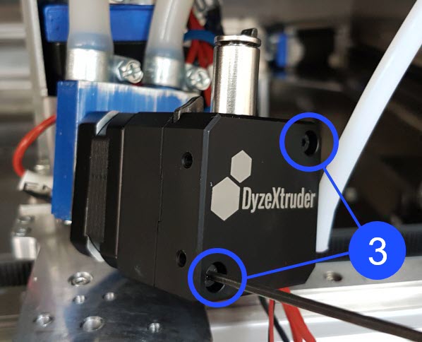
Use the 2 mm hex key to remove the two front cover screws (3) on the extruder assembly.
Internal extruder components are small and can fall when the sections are separated. Make sure to disassemble the extruder on a suitable work bench.
-
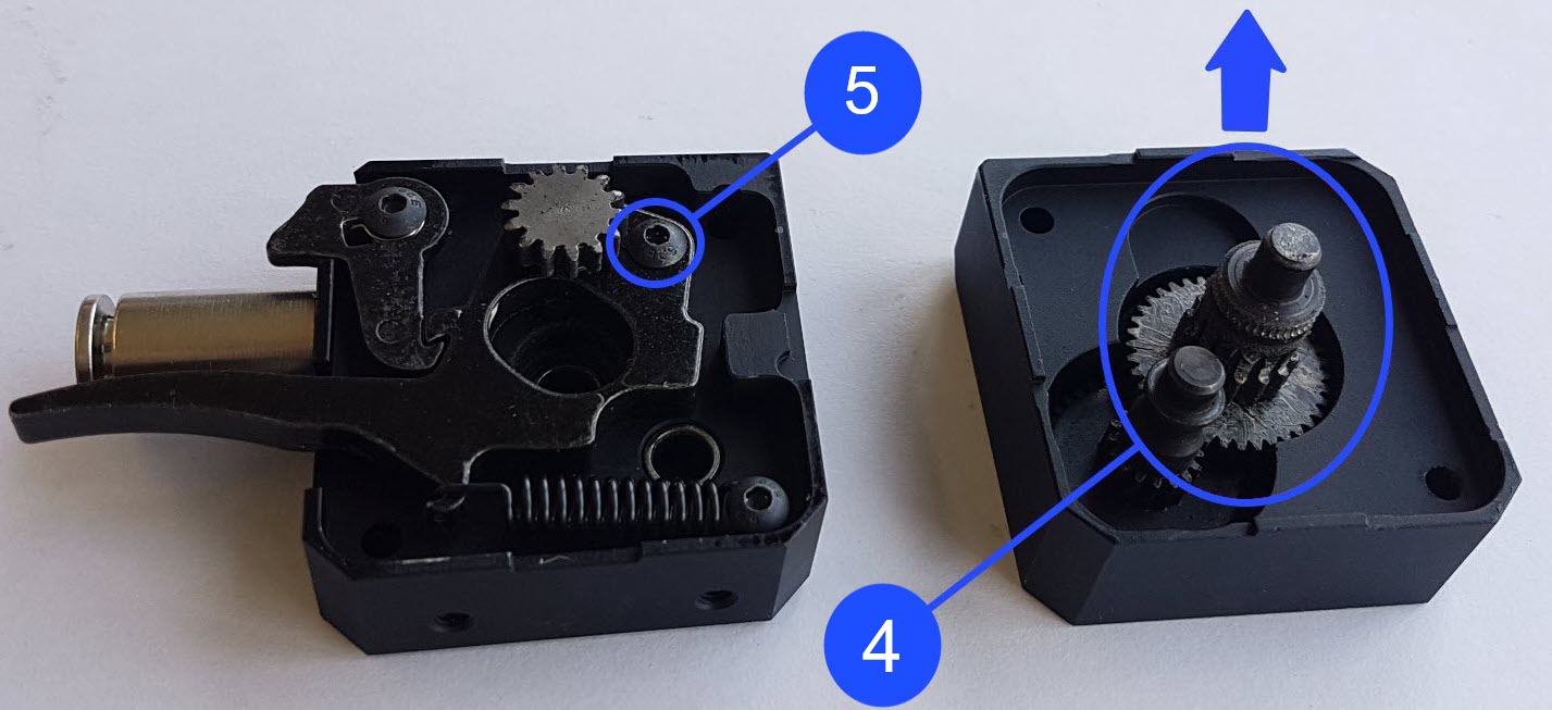
Carefully remove the extruder front and rear sections.
-
Use the pliers to remove the two gears (4) from the extruder cover.
-
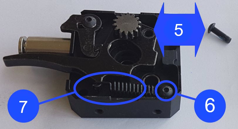
Use the 2 mm hex key to remove the two screws (5)(6).
-
Carefully lift the extruder lever assembly to release the spring (7).
Clean and Lubricate Extruder
- Use the small brush to remove all the filament debris found on the gears.
- Use the isopropyl alcohol and lint-free rag(s) to remove all contaminants from the gears.
- Inspect the two drive gears for wear and/or damages. Replace if necessary.
- Use the applicator brush to apply a small amount of white lithium grease to the teeth found on the four gears (8).
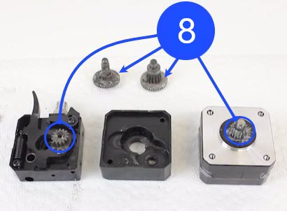
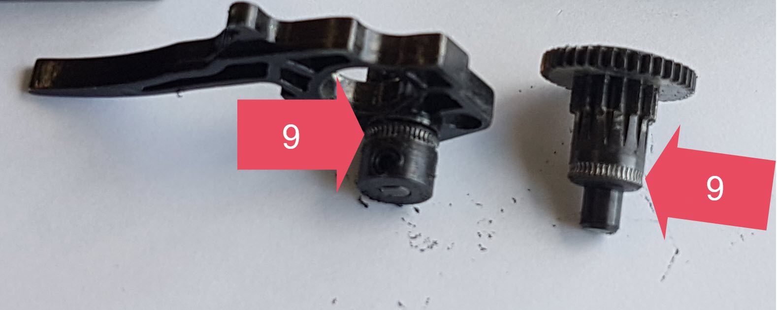
Do not apply white lithium grease the to filament radii (9). The filament radii (9) must operate dry. Lubrication on the filament radii (9) will cause unsatisfactory print quality and can cause damages to the machine component(s).
Assemble the Extruder
- Install the gears inside the extruder housing:
- Make sure that the gear teeth are lubricated with white lithium grease.
- Make sure that the gears are correctly positioned in the extruder housing.
- Manually install the screw (6) and tighten with the 2 mm hex key.
- Use the pliers to hook the top end of the spring (7) to the extruder lever assembly.
- Manually install the screw (5) and tighten with the 2 mm hex key.
- Position the extruder sections onto the motor. Make sure drive gear teeth mesh correctly.
- Manually install the two front cover screws (3). Do not tighten the two front screws (3) at this point in time.
Install the Extruder
- For AON M2+ (CE) and AON M2+ (R-NZ) machines, refer to Replace Extruders (AON M2+ (CE) & AON M2+ (R-NZ)).
- For AON M2+ machines, refer to Replace the Extruder (AON M2+).
- For AON-M2 2020 and AON-M2 machines, refer to Replace the Extruder.
Test and Return to Service
- Make sure that you remove all the tools from the build chamber.
- Close the build chamber door.
-
- For AON M2+ (CE) machines: Connect power to the machine from the local supply disconnecting device.
- For AON M2+ (R-NZ), AON M2+, AON-M2 2020 and AON-M2 machines: Connect the main power cord to the receptacle.
- Turn the power ON with the ON/OFF switch found on the rear panel of the machine.
- Release the E-stop button.
- Home XYZ.