Inspect and Adjust X/Y-Axes Perpendicularity
| Model | [•] AON M2+ (CE) | [•] AON M2+ (R-NZ) | [•] AON M2+ | [•] AON-M2 2020 | [•] AON-M2 |
| Category | [•] Preventive | [•] Corrective | |||
| Frequency | [ ] Daily | [ ] Weekly | [•] Monthly | [ ] Yearly | [ ] As Needed |
Summary
The procedure that follows gives instructions on how to inspect and adjust the X/Y-axes perpendicularity.
Estimated time: 60 minutes
Perpendicular X/Y-axes prevent:
- X-axis and/or Y-axis binding.
- Loud noises when the axes move.
- Premature wear of machine components.
- Unsatisfactory print layer quality.
Tools
| Qty | Description | Specification |
|---|---|---|
| 1 | Machinist Block | 1-2-3 inch, standard issue |
| 1 | Feeler Gauge | 0.003 inch (0.076 mm), blade-type |
| 1 | Hex Key | 4 mm |
| 1 | Hex Key | 2.5 mm |
| A/R | Rags | Lint-free |
| A/R | Isopropyl Alcohol | 99% |
| A/R | Cardboard Sheet | Approx. 200 mm wide x 400 mm length (8 inches x 16 inches) |
Parts Information
None required.
Personal Protective Equipment
| Qty | Description | Minimum Specification |
|---|---|---|
| 1 | Safety Eyewear | ANSI/ISEA Z87.1 |
| A/R | Nitrile Gloves | ISO 2859-1 or ASTM D6319 |
Prepare the Machine
Make sure that there are no prints on the build surface. Remove print(s) before the procedure that follows is started. Failure to do so can cause a collision and cause damage to the machine component(s).
- Home XYZ.
- Lower the Z-axis by 100 mm.
- Open the build chamber door.
- Push the E-stop button.
- Wait until the build chamber, build platform and hot ends are at room temperature.
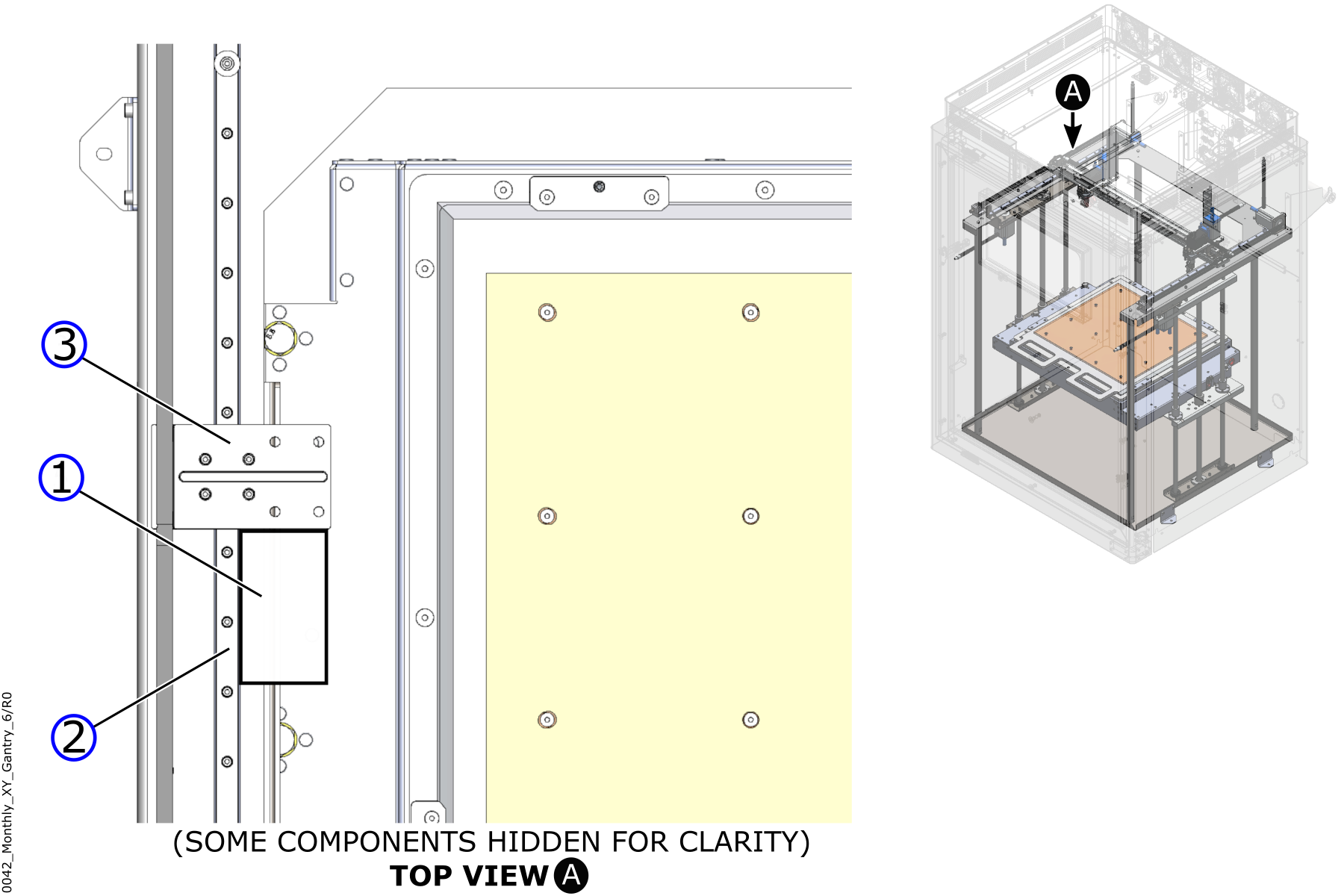
Inspect X/Y-Axes Perpendicularity
Wait until all machine components are at room temperature before you continue. Some machine components can be hot if the machine was recently used. Failure to do so can cause injuries.
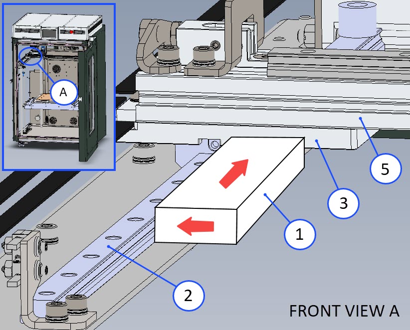
- Manually place the X-axis gantry to the center of the Y-axis.
- Use the isopropyl alcohol and a clean lint-free rag to clean the two Y-axis linear rail (2) and the two mounting plate (3) surfaces.
- Put the machinist block (1) in contact with both the inside of the left Y-axis linear rail (2) and the left mounting plate (3) face found under the X-axis assembly (5). Hold the machinist block (1) in this position.
- Use the 0.003 inch (0.076 mm) feeler gauge to make sure that there is no space between the machinist block (1) and the left mounting plate (3) face found under the X-axis assembly (5).
- Do steps 2 to 4 on the right side of the Y-axis gantry.
- If the Y-axis linear rail (2) and the mounting plate (3) under the X-axis assembly (5) are not perpendicular, refer to Adjust X/Y-Axes Perpendicularity.
- Remove the machinist block (1) and 0.003 inch (0.076 mm) feeler gauge.
Adjust X/Y-Axes Perpendicularity
- Put the cardboard sheet onto the build surface to prevent damage.
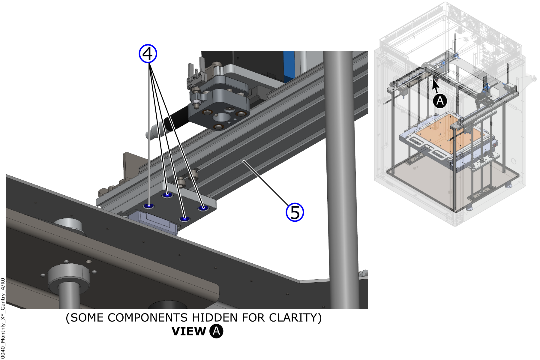
- Remove the X-axis assembly (5) from the two mounting plates (3):
- On the left side of the Y-axis gantry, use the 4 mm hex key to remove the four screws (4) from under the X-axis assembly (5).
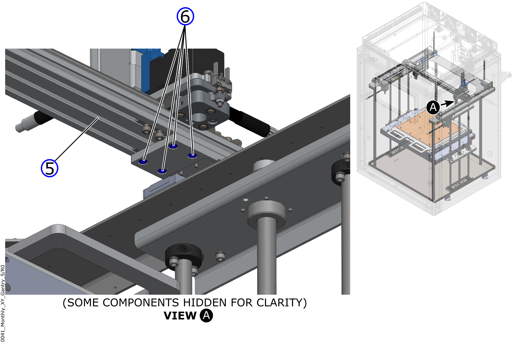
- On the right side of the Y-axis gantry, use the 4 mm hex key to remove the four screws (6) from under the X-axis assembly (5).
Do not twist and/or pull on the X-axis assembly (5) too much. The X-axis assembly (5) has multiple wires and tubes attached to it. Failure to do so will damage the machine components.
- On the left side of the Y-axis gantry, use the 4 mm hex key to remove the four screws (4) from under the X-axis assembly (5).
- Carefully remove the X-axis assembly (5) and place it on the build plate.
- Adjust the mounting plates (3) as follows:
- Use the isopropyl alcohol and a clean lint-free rag to clean the two mounting plate (3) top surfaces.
- Use the 2.5 mm hex key to loosen the four screws (7) that hold the left mounting plate (3) into position. Do not remove the four screws (7).
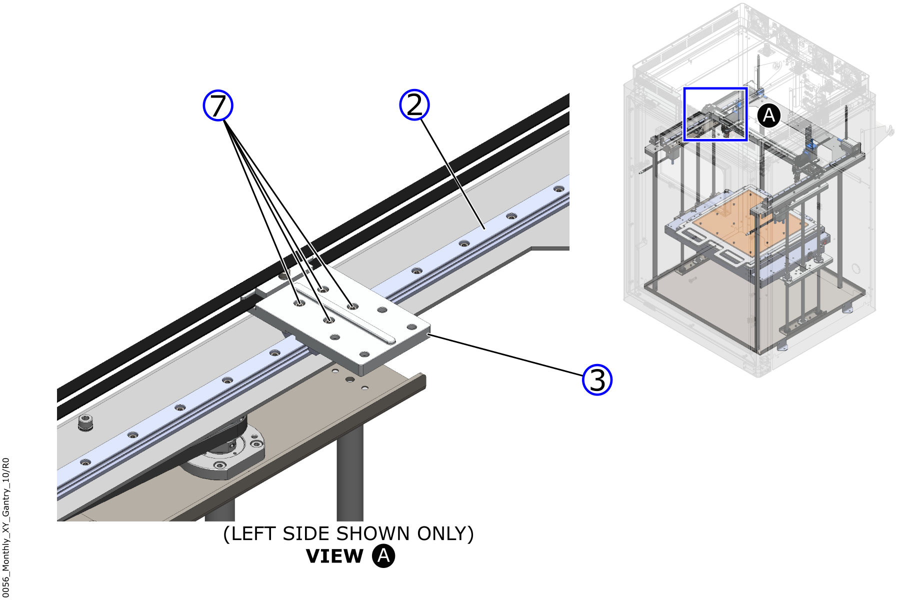
- Put the machinist block (1) in contact with both the inside of the left Y-axis linear rail (2) and the left mounting plate (3) face found under the X-axis assembly (5). Hold the machinist block (1) in this position.
- Carefully push the mounting plate (3) against the machinist block (1) to create a 90 degree angle between the Y-axis linear rail (2) and the left mounting plate (3).
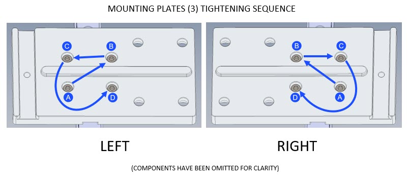
- Use the 2.5 mm hex key to gradually tighten the four screws (7), in a criss-cross pattern, to lock the mounting plate (3) into position. Do not tighten too much.
- Put the machinist block (1) in contact with both the inside of the left Y-axis linear rail (2) and the left mounting plate (3) face found under the X-axis assembly (5). Hold the machinist block (1) in this position.
- Use the 0.003 inch (0.076 mm) feeler gauge to make sure that there is no space between the machinist block (1) and the left mounting plate (3) face found under the X-axis assembly (5).
- If a clearance is present, do steps 3b to 3g as necessary.
- Do steps 3b to 3h on the right side of the Y-axis gantry.
- Remove the machinist block (1) and 0.003 inch (0.076 mm) feeler gauge.
- Use the isopropyl alcohol and a clean lint-free rag to clean the underside surface of the X-axis assembly (5) as necessary. Let surface dry for five minutes.
- Do the steps that follow to install the X-axis assembly:
Do not twist and/or pull on the X-axis assembly (5) too much. The X-axis assembly (5) has multiple wires and tubes attached to it. Failure to do so will damage the machine components.
- Carefully put the Y-axis assembly (5) into position on the two mounting plates (3).
- Install the four screws (4) through the left-side mounting plate (3) and into the Y-axis assembly (5). Do not tighten the four screws (4) at this point in time.
- Install the four screws (6) through the right-side mounting plate (3) and into the Y-axis assembly (5). Do not tighten the four screws (6) at this point in time.
- Use the 4 mm hex key to gradually tighten the eight screws (4)(6) into the Y-axis assembly (5) in a criss-cross pattern. Do not tighten too much.
- Make sure that all eight screws (4)(6) are tight.
- Remove and discard the cardboard sheet.
- Use a lint-free rag and isopropyl alcohol to clean the build surface as necessary.
- Let the build surface dry for two minutes.
Test and Return to Service
- Make sure that you remove all the tools from the build chamber.
- Close the build chamber door.
- Release the E-stop button.
- Home XYZ.
- Lower the Z-axis by 100 mm.
- Move the X-axis gantry approximately 200 mm in both directions.
- Home XYZ.
- Make sure there are no unusual noises and/or vibrations in the X/Y-axes.
- Do steps 5 to 8 two times.