Inspect and Tighten XYZ-Axes Microswitches
| Model | [ ] AON M2+ (CE) | [ ] AON M2+ (R-NZ) | [ ] AON M2+ | [•] AON-M2 2020 | [•] AON-M2 |
| Category | [•] Preventive | [ ] Corrective | |||
| Frequency | [•] Daily | [ ] Weekly | [ ] Monthly | [ ] Yearly | [ ] As Needed |
For instructions on how to inspect and tighten the XYZ-axes microswitches found on the AON M2+ (CE), AON M2+ (R-NZ) and AON M2+, refer to the Inspect and Tighten XYZ-Axes Microswitches (M2+) procedure.
For instructions on how to inspect, adjust and tighten the two probe microswitches found on the AON-M2 and the AON-M2 2020, refer to the Inspect, Adjust and Tighten Probe Microswitches procedure.
Summary
The procedure that follows gives instructions on how to:
- Inspect and tighten the two X-axis microswitches.
- Inspect and tighten the two Y-axis microswitches.
- Inspect and tighten the two Z-axis microswitches.
Estimated time: 30 minutes
Microswitches in good condition prevent:
- Unwanted interference between the XYZ-axes when machine components are in motion.
- Incorrect XYZ-axes reference points.
- Unsatisfactory print layer quality.
Tools
| Qty | Description | Specification |
|---|---|---|
| 1 | Wrench | 1/4 inch |
| 1 | Screwdriver | Phillips Head, No.2 |
| 1 | Hex Key | 5/64 inch |
| 1 | Hex Key | 4 mm |
| 1 | Hex Key | 1.5 mm |
Parts Information
None required.
Personal Protective Equipment
| Qty | Description | Minimum Specification |
|---|---|---|
| 1 | Safety Eyewear | ANSI/ISEA Z87.1 |
| A/R | Nitrile Gloves | ISO 2859-1 or ASTM D6319 |
Prepare the Machine
Make sure that there are no prints on the build surface. Remove print(s) before the procedure that follows is started. Failure to do so can cause a collision and cause damage to the machine component(s).
- Home XYZ.
- Lower the Z-axis by 300 mm.
- Push the E-stop button.
- Open the build chamber door.
- Wait until the build chamber, build platform and hot ends are at room temperature.
Inspect and Tighten Microswitches
Inspect and Tighten X-Axis Microswitches
Wait until all machine components are at room temperature before you continue. Some machine components can be hot if the machine was recently used. Failure to do so can cause injuries.
Do not tighten the microswitch fasteners too much. Failure to do so can cause damage to the microswitches, which can cause collisions of machine component(s).
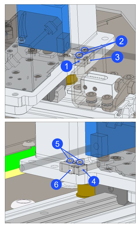
Right Microswitch
- Inspect the right X-axis microswitch (1).
- Make sure that the X-axis microswitch (1) has no cracks and/or defects. Replace if necessary. Refer to Replace X-Axis Microswitches.
- Make sure that the two X-axis microswitch screws (2) are tight.
- Use the Phillips screwdriver to lightly tighten the two screws (2), if necessary. Do not tighten too much.
- Use your finger to lightly compress the microswitch actuator (3), and release. Do this step three times.
- Listen for a click when the microswitch actuator (3) is compressed, and a click when the microswitch actuator (3) is released.
- If the microswitch actuator (3) does not function correctly, use the Phillips screwdriver to loosen the two screws (2), and lightly tighten the two screws (2) again. Do not tighten too much.
- Make sure that the microswitch actuator (3) functions correctly. Test the X-axis microswitch (1), if necessary. Refer to the Test Microswitches procedure.
- Test the X-axis microswitch, if necessary. Refer to the Test Microswitches procedure.
- Calibrate the X/Y toolhead offsets. Refer to X/Y Toolhead Offsets Calibration.
Left Microswitch
- Inspect the left X-axis microswitch (4).
- Make sure that the X-axis microswitch (4) has no cracks and/or defects. Replace if necessary. Refer to Replace X-Axis Microswitches.
- Make sure that the two X-axis microswitch screws (5) are tight.
- Use the Phillips screwdriver to lightly tighten the two screws (5), if necessary. Do not tighten too much.
- Use your finger to lightly compress the microswitch actuator (6), and release. Do this step three times.
- Listen for a click when the microswitch actuator (6) is compressed, and a click when the microswitch actuator (6) is released.
- If the microswitch actuator (6) does not function correctly, use the Phillips screwdriver to loosen the two screws (5), and lightly tighten the two screws (5) again. Do not tighten too much.
- Make sure that the microswitch actuator (6) functions correctly. Test the X-axis microswitch (4), if necessary. Refer to the Test Microswitches procedure.
- Test the X-axis microswitch, if necessary. Refer to the Test Microswitches procedure.
- Calibrate the X/Y toolhead offsets. Refer to X/Y Toolhead Offsets Calibration.
Inspect and Tighten Y-Axis Microswitches
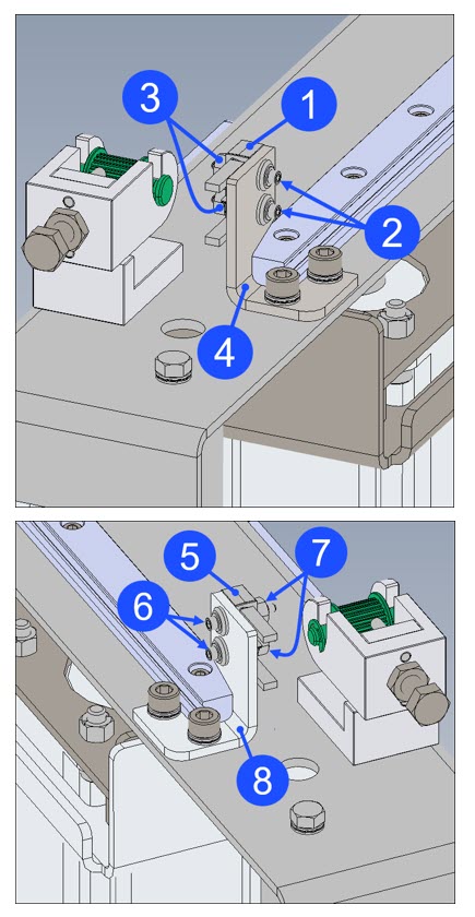
Left Microswitch
- Inspect the left Y-axis microswitch (1).
- Make sure that the Y-axis microswitch (1) has no cracks and/or defects. Replace if necessary. Refer to Replace Y-Axis Microswitches.
- Make sure that the two Y-axis microswitch screws (2) and two nuts (3) are tight.
- Use the 5/64 inch hex key and the 1/4 inch wrench to lightly tighten the two screws (2) and two nuts (3), if necessary. Do not tighten too much.
- Make sure that the Y-axis microswitch (1) is tight on the Y-axis end stop bracket (4).
- Use your finger to lightly compress the microswitch actuator, and release. Do this step three times.
- Listen for a click when the microswitch actuator is compressed, and a click when the microswitch actuator is released.
- If the microswitch actuator does not function correctly, loosen the two screws (2) and the two nuts (3), and lightly tighten the two screws (2) and the two nuts (3) again. Do not tighten too much.
- Make sure that the microswitch actuator functions correctly. Test the Y-axis microswitch (1), if necessary. Refer to the Test Microswitches procedure.
- Test the Y-axis microswitch, if necessary. Refer to the Test Microswitches procedure.
- Calibrate the X/Y toolhead offsets. Refer to X/Y Toolhead Offsets Calibration.
Right Microswitch
- Inspect the right Y-axis microswitch (5).
- Make sure that the Y-axis microswitch (5) has no cracks and/or defects. Replace if necessary. Refer to Replace Y-Axis Microswitches.
- Make sure that the two Y-axis microswitch screws (6) and two nuts (7) are tight.
- Use the 5/64 inch hex key and the 1/4 inch wrench to carefully tighten the two screws (6) and two nuts (7), if necessary. Do not tighten too much.
- Make sure that the Y-axis microswitch (5) is tight on the Y-axis end stop bracket (8).
- Use your finger to lightly compress the microswitch actuator, and release. Do this step three times.
- Listen for a click when the microswitch actuator is compressed, and a click when the microswitch actuator is released.
- If the microswitch actuator does not function correctly, loosen the two screws (6) and the two nuts (7), and lightly tighten the two screws (6) and the two nuts (7) again. Do not tighten too much.
- Make sure that the microswitch actuator functions correctly. Test the Y-axis microswitch (5), if necessary. Refer to the Test Microswitches procedure.
- Test the Y-axis microswitch, if necessary. Refer to the Test Microswitches procedure.
- Calibrate the X/Y toolhead offsets. Refer to X/Y Toolhead Offsets Calibration.
Inspect and Tighten Z-Axis Microswitches
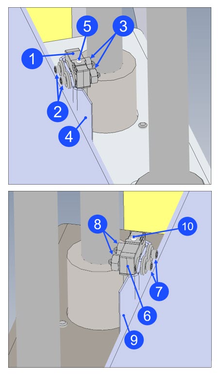
Right Microswitch
- Inspect the right Z-axis microswitch (1).
- Make sure that the microswitch (1) has no cracks and/or defects. Replace if necessary. Refer to Replace Z-Axis Microswitches.
- Make sure that the two Z-axis microswitch screws (2) and two nuts (3) are tight.
- Use the 5/64 inch hex key and the 1/4 inch wrench to carefully tighten the two screws (2) and two nuts (3), if necessary. Do not tighten too much.
- Make sure that the Z-axis microswitch (1) is tight on the Z-axis end stop bracket (4).
- Use your finger to carefully compress the microswitch actuator (5), and release. Do this step three times.
- Listen for a click when the microswitch actuator (5) is compressed, and a click when the microswitch actuator (5) is released.
- If the microswitch actuator (5) does not function correctly, loosen the two screws (2) and the two nuts (3), and carefully tighten the two screws (2) and the two nuts (3) again. Do not tighten too much.
- Make sure that the microswitch actuator (5) functions correctly. Test the Z-axis microswitch (1), if necessary. Refer to the Test Microswitches procedure.
- Test the Z-axis microswitch, if necessary. Refer to the Test Microswitches procedure.
- Calibrate the Z-axis. Refer to Z Offset Calibration.
Left Microswitch
- Inspect the left Z-axis microswitch (6).
- Make sure that the microswitch (6) has no cracks and/or defects. Replace if necessary. Refer to Replace Z-Axis Microswitches.
- Make sure that the two Z-axis microswitch screws (7) and two nuts (8) are tight.
- Use the 5/64 inch hex key and the 1/4 inch wrench to carefully tighten the two screws (7) and two nuts (8), if necessary. Do not tighten too much.
- Make sure that the Z-axis microswitch (6) is tight on the Z-axis end stop bracket (9).
- Use your finger to carefully compress the microswitch actuator (10), and release. Do this step three times.
- Listen for a click when the microswitch actuator (10) is compressed, and a click when the microswitch actuator (10) is released.
- If the microswitch actuator (10) does not function correctly, loosen the two screws (7) and the two nuts (8), and carefully tighten the two screws (7) and the two nuts (8) again. Do not tighten too much.
- Make sure that the microswitch actuator (10) functions correctly. Test the Z-axis microswitch (6), if necessary. Refer to the Test Microswitches procedure.
- Test the Z-axis microswitch, if necessary. Refer to the Test Microswitches procedure.
- Calibrate the Z-axis. Refer to Z Offset Calibration.
Test and Return to Service
- Make sure that you remove all the tools from the build chamber.
- Close the build chamber door.
- Release the E-stop button.
- Home XYZ.